


The metering type paint filling machine is controlled by PLC. On the capping machine, there are dedicated sensors. PLC issues instructions to control the capping machine to perform the capping action. After the capping is completed, the bucket stopper retracts, and the conveyor belt transports the buckets to the next labeling machine position. The specialized labeling machine automatically senses the buckets conveyed by the conveyor belt and completes the automatic labeling of the buckets. The servo system is used to control the operation and stop of the motor, thereby ensuring the motion accuracy of the buckets throughout the filling process.

 020-34563445
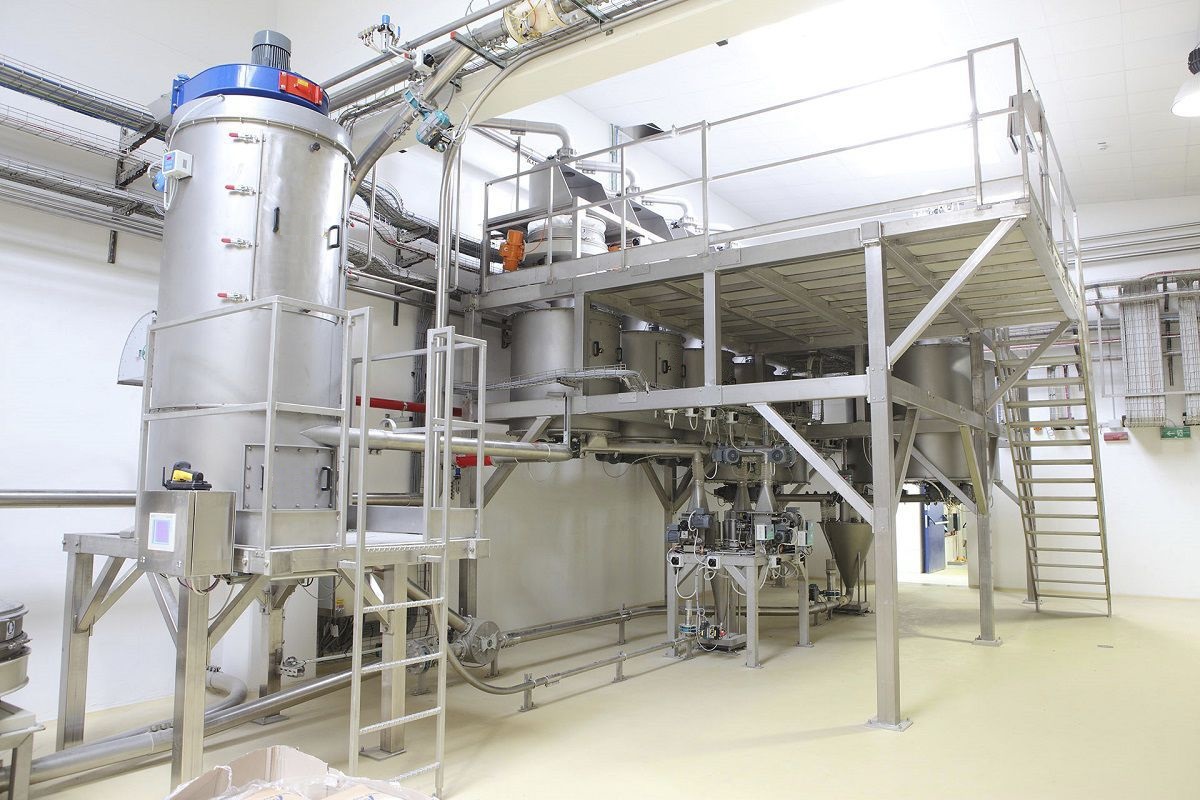
The automatic Filling machine is controlled by PLC for the inlet and outlet transfer buckets, infrared positioning, Electronic scale measurement, automatic control of the feeding pump function, automatic zeroing of the weighing instrument, real-time display of the weighing value, dual protection of emergency stop/ power failure, and automatic alarm for out-of-tolerance conditions. A counter device is set up to calculate and record the number of buckets, and the counter is connected to the PLC. The count quantity is set and displayed through the touch screen. Two bucket stop valves are set on the automatic filling machine. When an empty bucket passes by the front bucket stop valve, it will automatically stop the bucket, and at the same time, the rear bucket stop valve also starts the bucket stop action, and the filling equipment begins the filling operation. The filling port is controlled by an electromagnetic valve and a filling gun to ensure the accuracy of the filling volume and the consistency of the filling quantity. Both the electromagnetic valve and the filling gun are controlled by the PLC. Special sensors are configured on the capping machine to detect whether the bucket is in place. When the bucket reaches the designated position, the PLC issues an instruction to control the capping machine to perform the capping action. After the capping is completed, the bucket stop valve retracts, and the conveyor belt conveys the bucket to the next labeling machine position. The specialized labeling machine automatically senses the bucket and starts the labeling action to complete the automatic labeling of the bucket. The automatic inkjet printer on the production line can sense the bucket and perform the automatic inkjet operation. The servo system is used to control the operation of the motor and its stop, in order to ensure the motion accuracy of the bucket during the entire filling process.
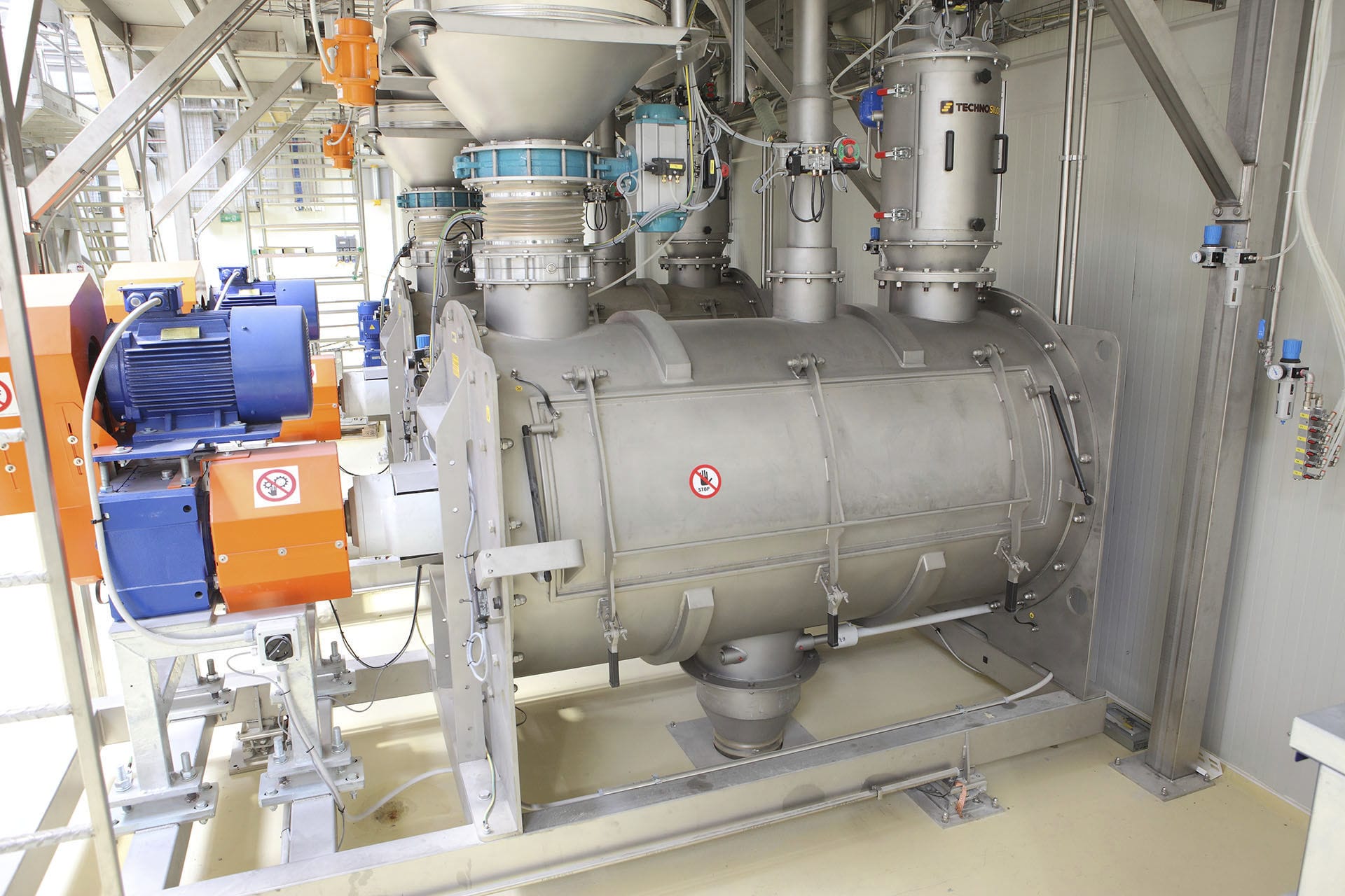
The Liquid filling machine controls the barrels through the bucket divider and the fixed bucket holder. The front and rear baffles cooperate with the chain conveyor to perform the function of dividing the barrels. Before the bucket divider is activated, a barrel is placed between the front and rear baffles. The distance between the two baffles is exactly the distance of one barrel (the distance between the baffles can be adjusted to accommodate changes in barrel shape). The movement of the baffles is controlled by a timer, and multiple barrels are released each time. Initially, both baffles are in the extended position. During the bucket division process, the action of the baffles is as follows: the front baffle retracts, with a delay time of 1; the rear baffle retracts, followed by a delay time of 2; the front baffle extends, with a delay time of 3; and the rear baffle extends. These four actions are repeated multiple times to complete the separation of multiple barrels. The spacing of the separated barrels is achieved by adjusting the conveying speed of the chain conveyor and the delay time.
The control of the bucket positioning is also achieved through a timer. There are multiple bucket positioning devices, each driven by a cylinder. The distance between the bucket positions is consistent with the spacing of the conveyor belt support plate. When the first bucket separated by the bucket divider passes the photoelectric switch, the timer starts timing. After the set time, the first bucket positioning cylinder extends to block the position of the first bucket; when the second bucket passes the photoelectric switch, the timer starts timing, and after the set time, the second bucket positioning cylinder extends. This process repeats to complete the positioning of multiple buckets. Due to the fast running speed of the chain plate, multiple buckets move continuously. The extension time of the bucket stopper needs to be precisely controlled, and it requires multiple controls to determine the accurate time of each timer. After the positioning of multiple buckets, they are pushed to the bucket storage area by the pusher plate during the filling process, preparing the conveyor belt to carry the filled buckets to the filling position.
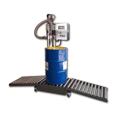
To ensure that the filled buckets are accurately delivered to the nozzle of the spray gun, the stop position of the conveyor belt must be precisely controlled. The speed control of the conveyor belt is achieved by a frequency converter. Properly setting the start and stop times of the frequency converter can make the control of the conveyor belt more accurate and stable. The positioning is carried out by using the photoelectric switch to detect the position of the conveyor belt. Using the pulse front of the photoelectric switch as the reference, when the last conveyor belt reaches 1 second before the end, the frequency converter is made to run slowly, causing the conveyor belt to stop at a more accurate position. After multiple controls, the position error of the conveyor belt does not exceed 5mm, usually around 2mm. To ensure that the spray gun can reliably enter the bucket opening during the descent, mechanical bucket opening positioning devices are installed at both ends of the filling position. Before the spray gun descends, the bucket opening positioning device is activated to ensure that the spray gun can smoothly enter the bucket. The filling process is completed by PLC and weighing instruments together. One weighing instrument corresponds to one electronic scale. The pre-Filling system automatically determines whether the skin weight value is within the set range. If it is less than the set skin weight value, the instrument does not perform the weight removal operation and does not start the filling process. This function can avoid the situation of incorrect filling caused by the bucket not being in place.


