


Multi-Stage Weighing and feeding system mainly displays multiple sensors and weighing instruments, and outputs multi-stage control signals. Users can directly access PLC raw material system and terminal control system to realize multi-stage control and automatic control. According to the pre-determined formula, all kinds of different raw materials are mixed proportionally. In order to improve the accuracy and speed of batching, ensure the quality of products and increase the output, microcomputer control technology is adopted. Microcomputer-controlled matching production line.

 020-34563445
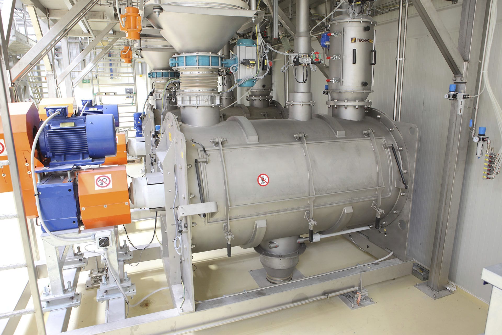
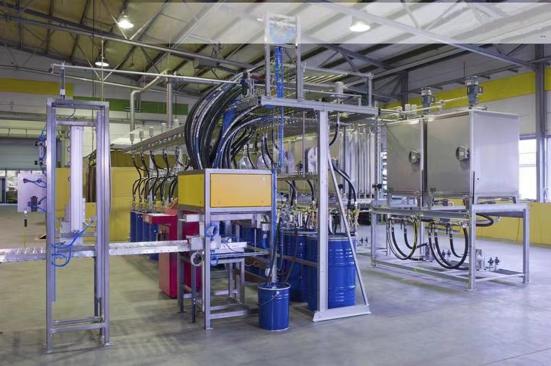
The multi-stage weighing and feeding system consists of two parts. The first part is the scale body, which includes the material bin, scale frame, screw, load weighing module, speed sensor, AC or DC drive motor and hidden speed machine, etc. The second part is the weighing instrument section: It includes weighing instruments, AC or DC speed control equipment and gate connection circuits, etc. Some multi-feed batching machines connect each Electronic scale to the factory's computer distributed control system for centralized control. The analog signals of the field instruments are transmitted to the computer signals, and a digital, bidirectional transmission, multi-branch communication network is formed to connect intelligent field equipment and automation systems.
The weighing feeding system mainly displays multiple weighing sensors and weighing instruments, and outputs multi-stage control signals. Users can directly access the PLC raw material system and terminal control system to achieve multi-stage control and automatic control. According to the pre-determined formula, various raw materials are mixed in proportion. To enhance the accuracy and speed of batching, ensure product quality and increase output, microcomputer control technology is adopted. Microcomputer-controlled cooperative production line.
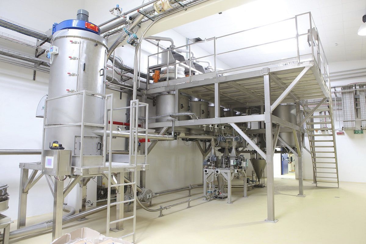
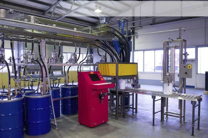
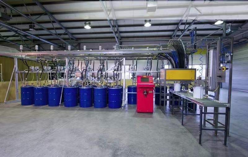
The feeding system must adjust the amount of feed discharged by the screw per unit time for measurement. By adjusting the rotation Angle of the screw per unit time, the amount of feed discharged per unit time can be changed. At the bottom of each raw material silo, there is a feeding pipe (pipe diameter DN65), which is controlled by automatic valves and manual valves respectively. The automatic valve for each type of powder is installed near the pipe outlet. The feeding pump is responsible for sending the material through the pipe to the metering silo. An automatic valve is installed at the feeding port of the metering silo to achieve fast and slow feeding control of the material.
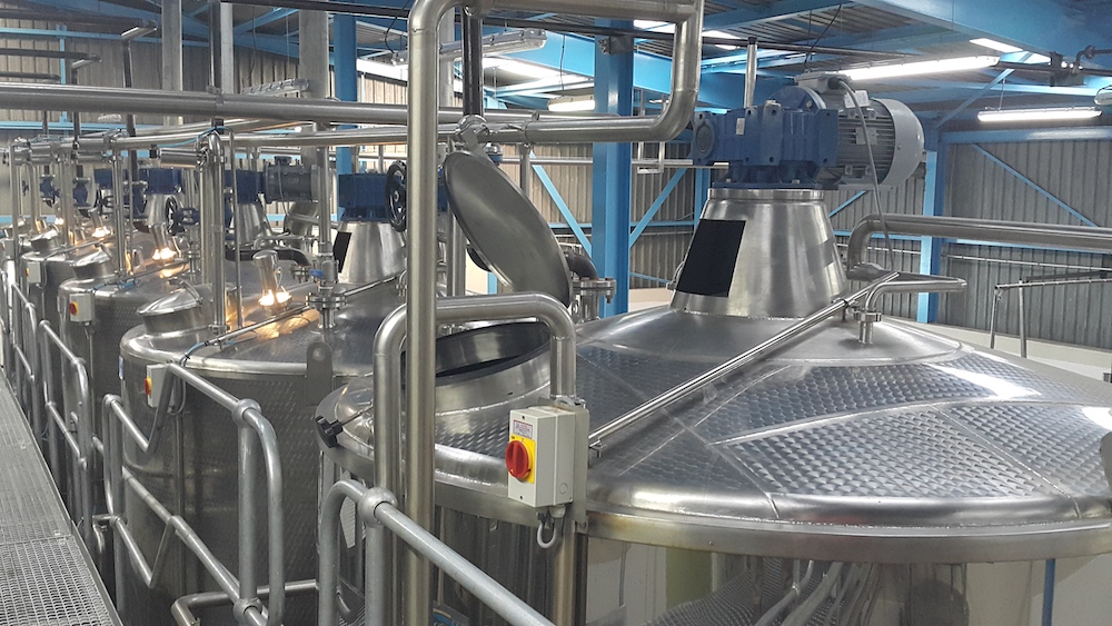
A weighing module is installed between each of the four support feet of the metering bin and the foundation of the support frame, responsible for measuring the weight of the materials entering the metering bin. The foundation of the support frame needs to be leveled. After the raw materials are measured, they are automatically added to the corresponding mixing bins through the automatic diversion device at the bottom of the metering bin. After the main discharge valve of the metering silo is installed horizontally to the automatic valves for material distribution in each mixing silo, the front feeding pipes of each automatic valve for material distribution are connected by pipelines. This can ensure that there is basically no material remaining after discharge. The water and liquid material discharge pipelines to each mixing silo can be combined into one pipeline to reduce the cost of pipeline materials.


