









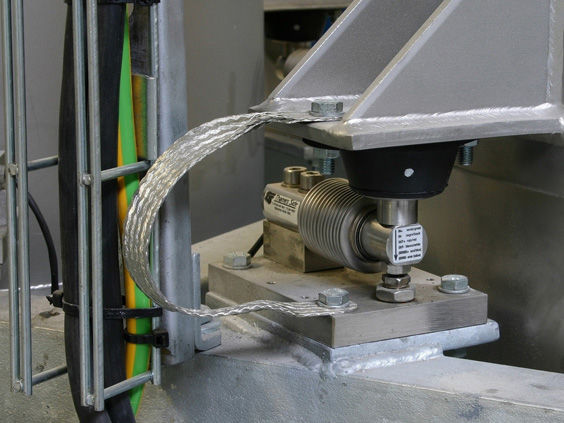
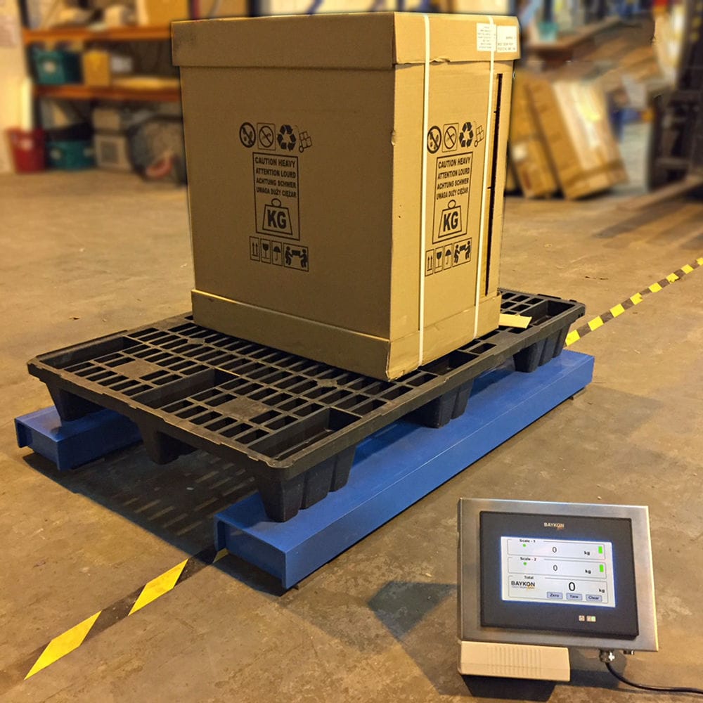


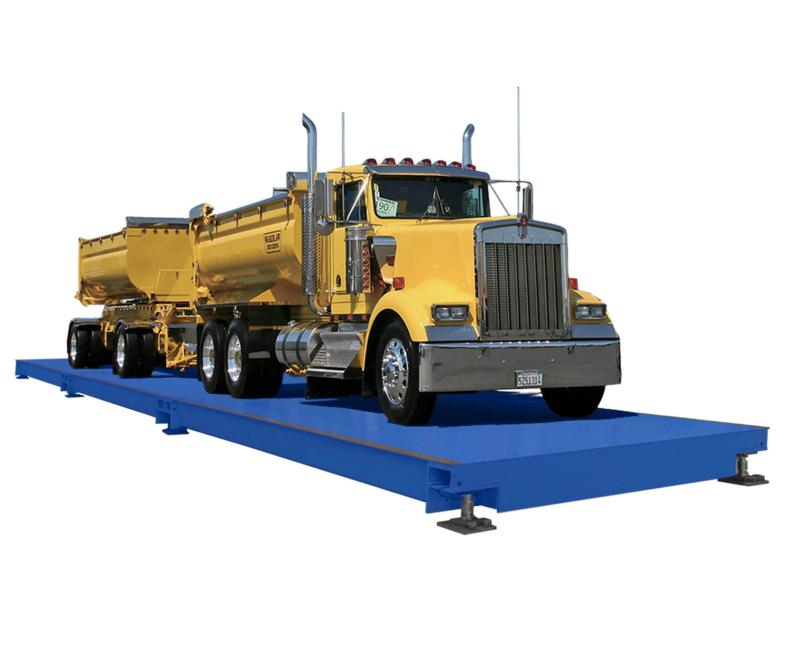
The floor scale and weighbridge calibrator adopts a weightless support device, including the weighbridge platform, standard weighing sensor, I-beam, weighing calibration instrument, jack, base, bracket, and crossbeam. On the side of the weighbridge pit, there are several I-beams on the weighbridge platform, and below the I-beams, there are weighing sensors. Above the I-beams, there are successively installed weighing calibration instruments and jacks. The weighing sensor is installed on the base, and the calibration bracket is installed on the base. The bracket is equipped with the crossbeam. The base of the standard weighing sensor is equipped with a hydraulic cylinder and a weighing calibration instrument, which is centered with the standard weighing sensor.

 020-34563445
An Electronic scale, as a material weighing device, according to the national metrological support regulations for digital electronic scales, the current calibration method used is the flashing method with standard weights. That is, the calibration standard weights (or other constant load substitutes) are placed on the load-bearing platform of the electronic scale and the weight (mass) of the weights is displayed through the weighing instrument. However, the current calibration method using online calibration is limited by many factors and cannot complete the calibration task. Firstly, the installation space of the electronic scale is limited and there is not enough space to support the calibration support frame. To address the shortcomings and deficiencies in the weighing process of the scale, a set of rapid calibration device for the scale was designed. The calibration device consists of vertical pull rods connected on both sides of the calibration support base and the weighing calibration instrument to form a rigid frame. The calibration base and the weighing calibration instrument are placed sequentially from bottom to top with the calibrated sensor, the base for positioning the calibrated weighing sensor, the standard weighing sensor base platform, and the jack placed on the jack, and the standard weighing sensor and the calibration support of the weighing calibration instrument are subjected to reverse force under the jack and simultaneously apply a uniform pressure to the standard weighing sensor. The distribution valve is connected to the hydraulic pump and the wiring box to link the weighing instrument. The hydraulic pump serves as the source of system force and replaces the weight of the weights. After completing the support of one scale, the jack and the weighing calibration instrument under the calibration support are removed. At this time, the calibration support and the standard weighing sensor are in an suspended state without any force, and the cover plate of the standard weighing sensor is covered and the screws are locked.
The weighing platform without weight support device, including the weighing platform, standard weighing sensor, I-beam, weighing calibration instrument, jack, base, bracket, crossbeam. On the side of the weighing platform inside the weighing pit, there are several I-beams. Below the I-beams, there are weighing sensors. Above the I-beams, there are successively installed weighing calibration instruments and jacks. The weighing sensors are installed on the base, and the calibration bracket is installed on the base. The bracket is equipped with a crossbeam. The standard weighing sensor base has a hydraulic cylinder and a weighing calibration instrument placed on it, which are centered with the standard weighing sensor. A force application hydraulic device is placed between the support platform and the frame. The weighing calibration instrument and the standard weighing sensor apply pressure and exert force to display their standard values. A pad plate can also be set between the hydraulic device and the top of the frame. This pad plate can be integrated with the frame.
When dealing with the non-weight-checking technology, a weighing device that can represent the known mass and is not a physical object such as weights is sought. The output voltage value corresponding to the force value (which corresponds to the applied mass) has been calibrated in the indication value of the sensor's bracket. As long as this value is stable, it is sufficient to represent the standard value of the mass. To reproduce the standard force (mass) value of the weighing sensor during verification, using a closed system and a force application frame is practical. The inspected electronic scale platform is supported by the weighing sensor, which is installed on the pressure plate, and the pressure plate is fixed to the reinforced concrete foundation. The foundation plate is welded with a U-shaped frame. To achieve the method of applying force with a standard weighing sensor, preparatory verification brackets need to be reserved on the original foundation and the original scale platform weighing transducer. During verification, the standard sensor is placed on the scale platform, and the jack is placed between the upper beam of the closed system frame and the weighing sensor. The jack is used to achieve the force application process. At this time, the multi-channel output signals of the weighing verification instrument and the weighing sensor (group) on the scale platform can be compared one by one, thereby measuring the accuracy of the scale without using weights.


