


Liquid Automatic filling machine using computers to achieve the human visual function, the machine instead of the human eye to do the measurement and judgment, the use of photoelectric imaging system to collect the image of the controlled target, by the computer or special image processing module for digital processing, according to the image of the pixel distribution, brightness and color information, such as size, shape, color and other identification. This organically combines the rapidity and repeatability of the computer with the high degree of intelligence and abstraction of the human eye's vision, which greatly improves the flexibility and automation of the production process inspection, saves a lot of manpower, improves inspection efficiency and ensures product quality.

 020-34563445
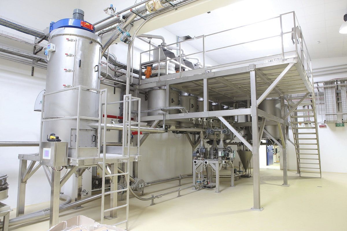
The material path of the quantitative automatic Filling machine is usually composed of a material tank feed control valve, an inlet tank, a valve group for the metering tank feed, a cylinder group (piston type), a filling feed control valve valve group, and a filling gun group. During the filling process, the material conveying pump transports the liquid material from the finished product storage tank through a pipeline to the filling machine inlet tank, and then through the cylinder feed control valve, cylinder, filling feed control valve, and filling gun into the bucket. The piston-type quantitative filling valve includes a valve seat and a valve core. The valve seat has a valve core hole, and on one side of the valve seat that faces the valve core hole, there is a end cover. The valve core has an inlet port on one side and a rotating shaft on the other side. The valve core is movably set in the valve core hole, and its rotating shaft passes through the end cover and is fixed with the driving arm. The upper side of the valve seat has an introduction port and an outlet port that are in communication with the valve core hole, and the lower side has a filling port that is in communication with the valve core hole. The valve core has an inlet channel that alternately connects the inlet port and the introduction port and a filling channel that connects the outlet port and the filling port. The upper end of the valve seat has a quantitative cylinder that is in communication with the introduction port and the outlet port, and the lower end has a filling nozzle that is in communication with the filling valve.
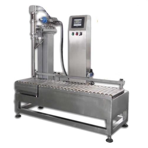
The automatic weighing filling machine is used for filling various solvents. Above the automatic filling machine, there is a constant pressure liquid storage tank (material box), which contains two spaced liquid level sensors. By controlling a rotating pneumatic valve for level control, the liquid level is kept stable. The material box is connected to the filling head. The filling head is controlled by the pneumatic valve, and the pneumatic valve is controlled by the Electronic scale to achieve dosage control. Its accuracy is guaranteed by selected high-quality components and software. The conveyor belt motor is controlled by a frequency converter, and an optical fiber sensor is set at the inlet bucket to detect the number of buckets. When multiple buckets are detected, the conveyor belt motor stops, and the cylinder at the outlet extends to block the empty bucket, while the cylinder at the inlet also extends and no longer fills the bucket. The filling head descends to the bucket mouth and the time input by the touch screen is controlled by the PLC to open the pneumatic valve on the filling head, for filling. After the filling is completed, the filling head rises, the cylinder at the outlet retracts, and the conveyor belt motor starts working again. After a 2-second delay, the cylinder at the inlet retracts, and the optical fiber sensor detects the number of buckets again. The above process repeats.
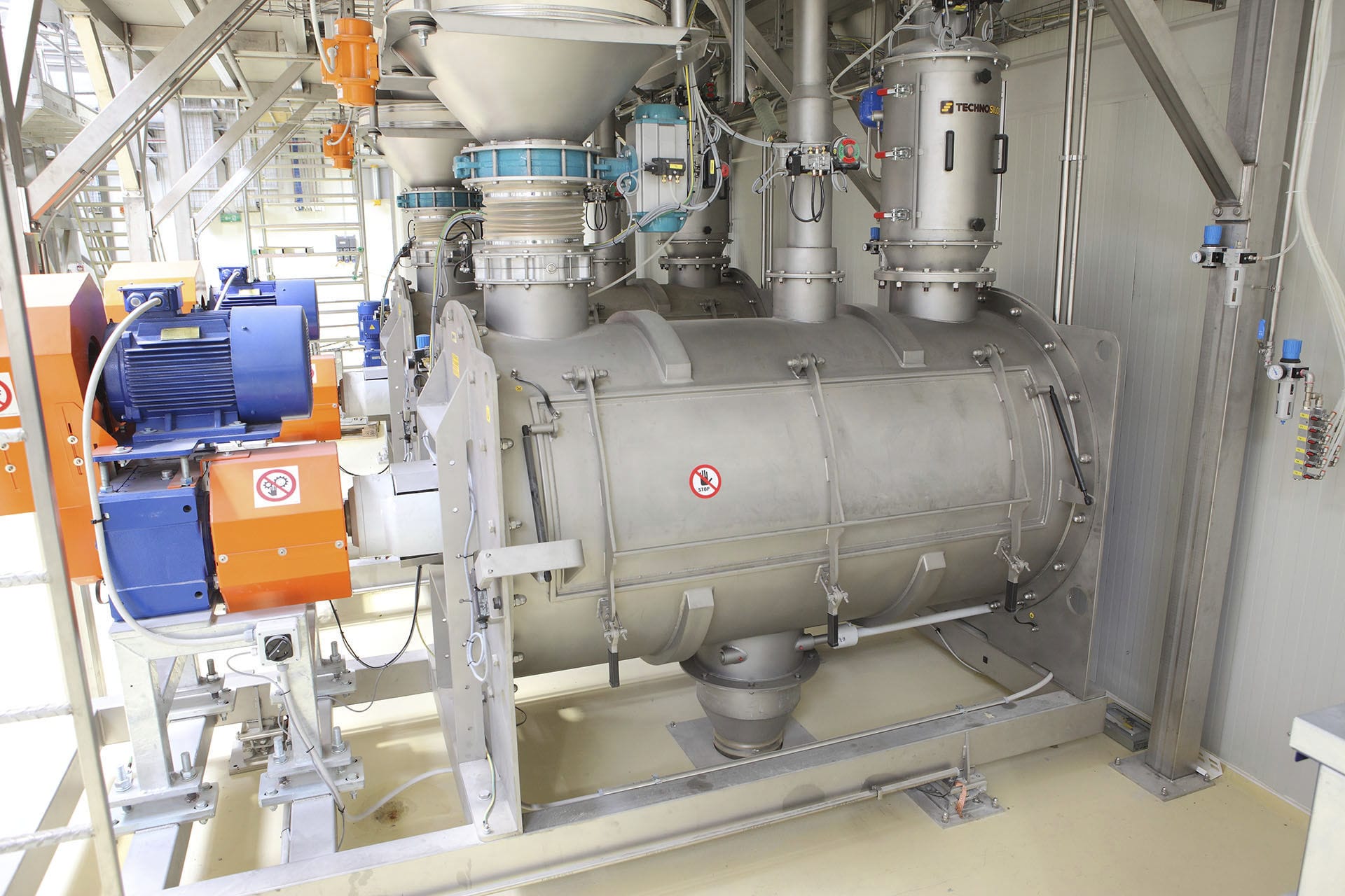
The filling gun of the automatic Liquid filling machine adopts a rotating groove per revolution with a certain volume. The electronic scale can precisely weigh the material by controlling the screw rotation number through its weight, and can further improve the weighing quality. The prerequisite for improving the weighing quality is to improve the accuracy of controlling the number of screws. A toothed belt drive can be used, and a small piston with a tower structure can be used to change the position of the toothed belt on the piston to well calculate the screw rotation number. To further improve the accuracy, a photoelectric encoder can be equipped on the screw. The power of the stirring motor is transmitted to the stirring rod through the transmission mechanism, and the stirring rod can well change the stress distribution of the material, thereby improving the flow state of the material and achieving the purpose of stabilizing the material bulk density, ultimately improving the measurement accuracy. When starting the measurement, the measurement motor makes the small piston drive the large piston to rotate, and the photoelectric encoder also starts to rotate. After receiving the signal, the electromagnetic clutch rotates when the screw shaft is engaged with the large piston and the clutch. When the measurement screw shaft and the photoelectric encoder rotate for the set number of turns, the electrical control system receives the signal, the large piston and the clutch are disengaged, and the brake also brakes. The packaging begins, and after the packaging is completed, the above actions are repeated.


