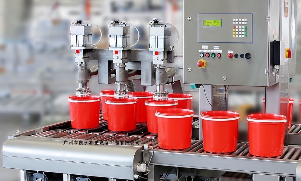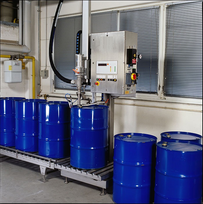


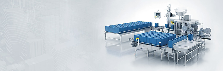


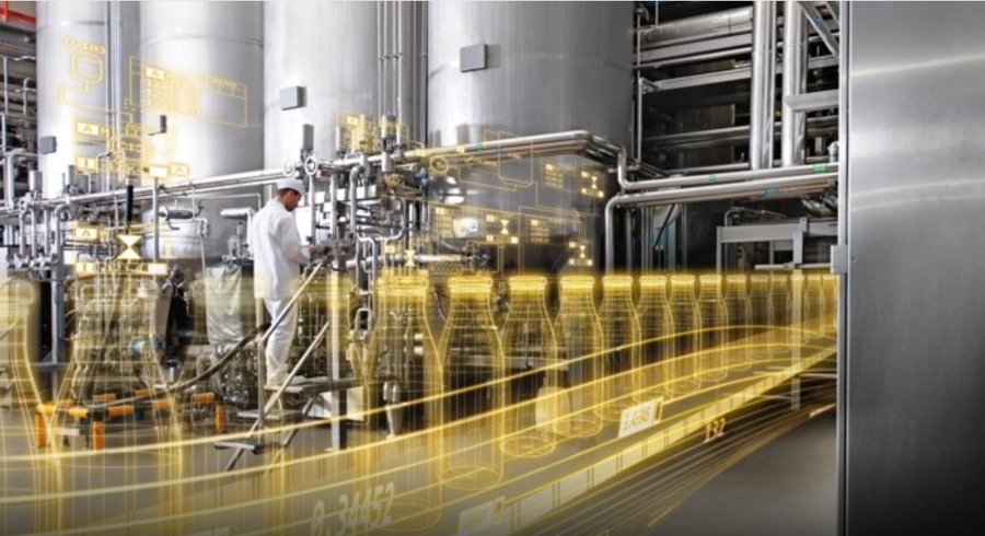
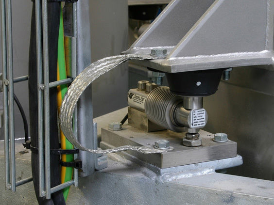
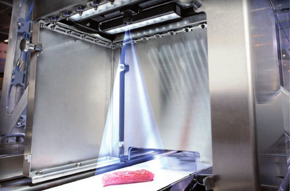


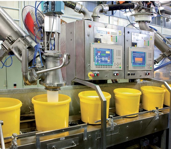
Automatic filling machine to realize the instrumentation and PLC and the host computer communication connection, real-time processing and the corresponding components of the formula for comparison of the settings. The use of RS485 bus type to realize the connection with the filling machine port, in order to achieve the instrumentation and PLC and the host computer running state is consistent, read through the interface stored in the filling machine touch screen, easy to fill management and query.

 020-34563445
The automatic barrel loader adopts speed control commands and operates in a 360 degree cycle. When the pause function program needs to pause the equipment, simply execute the command. When restarted, simply execute the command again and the device will resume running from the current stopped position. The advantage of pausing is that when the operator needs to temporarily stop the equipment for simple processing and then quickly restore production status, there is no need to search for the origin again. According to the characteristics of the crank mechanism, when the servo rotates at a constant speed, the liquid Filling machine can give different speeds when the filling servo reaches various positions, and achieve a basic constant vertical speed by giving "multi-stage speed" to the diagonal speed. By writing the speed every 10ms, the speed transformation can be achieved. Obtain the linear relationship between the servo angular position and the vertical position of the crankshaft through plane analytic geometry and trigonometric operations. In the end, the filling volume value in milliliters can be directly set on the touch screen. After the cam table is compiled, each head will repeat its movement according to its own cam table data. If the product is replaced (mainly due to changes in bottle size), the movement of individual heads will change. Through program transformation, the FOR loop statement is used to modify several points in the cam table one by one, and then saved using the following instruction. From scratch, the movement will be based on the new cam table.
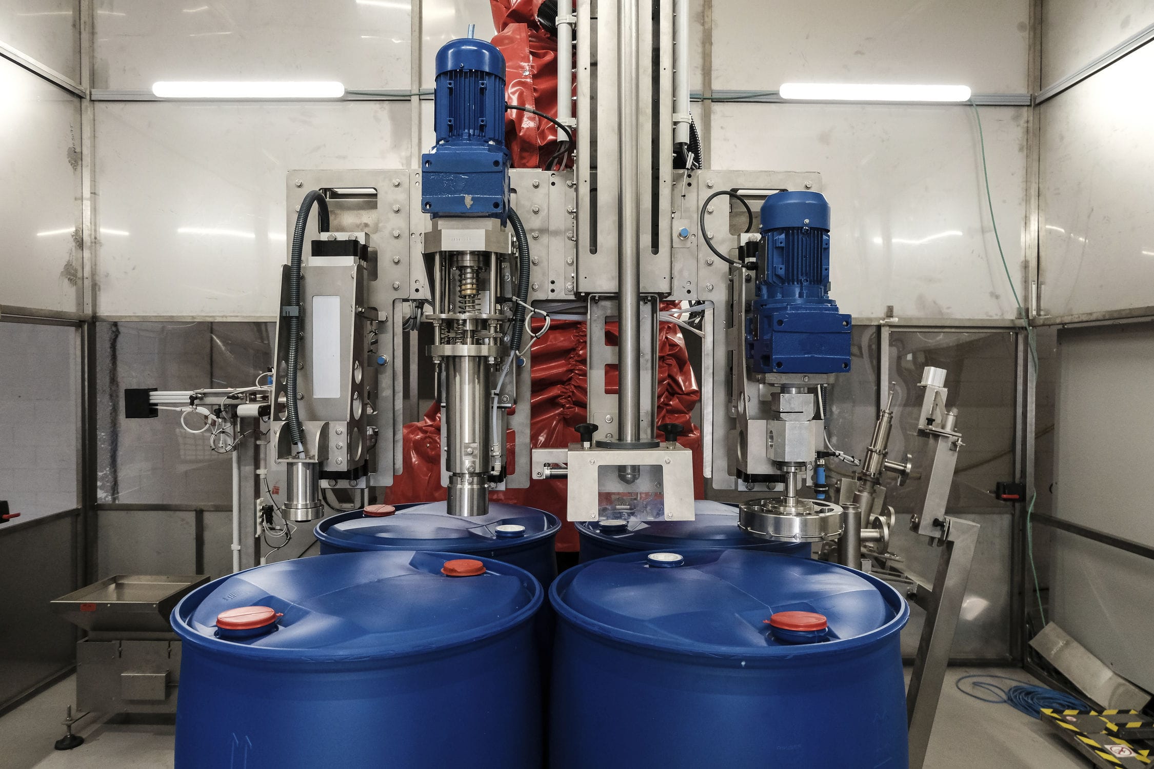
The quantitative filling machine has two horizontally symmetrical first clamping plates connected by sliding on the surface of the lower side wall of the machine body. The side walls of the two first clamping plates are connected to the first screw rod through threaded through holes, and the rotation direction of the two threaded through holes is opposite. The first screw rod penetrates the side wall of the machine body and is rotatably connected to it. One end of the first screw rod is fixedly connected to the first handle. The lower side wall of the machine body between the two first clamping plates is provided with a strip-shaped opening. The side walls of the strip-shaped opening are slidably connected to two symmetrically arranged second clamping plates. The side walls of the two second clamping plates are connected to the second screw rod through threaded through holes, and the rotation direction of the two threaded through holes is opposite. The second clamping plate penetrates the machine body. The side wall is set and rotatably connected to it, and one end of the second screw rod is fixedly connected to a second handle, Multiple material buckets are placed between the first and second clamping plates, and a filling device is installed above the buckets. The filling device uses a U-shaped mounting plate, and the upper side wall of the U-shaped mounting plate is connected to the first driving device, There are two horizontally arranged sliding rails fixedly connected between the two opposite side walls of the U-shaped installation plate. The side walls of the two sliding rails are slidably connected to multiple arrays of L-shaped plates. The horizontal end of the L-shaped plate is fixedly connected to a filling head on the side wall, and the end of the filling head away from the material bucket is fixedly connected to a feeding tube. The U-shaped installation plate is slidably connected to an adjustment plate on the side wall away from the first handle. The side wall of the adjustment plate is connected to a second driving device. The side wall of the adjustment plate is provided with a vertically arranged first sliding groove, multiple obliquely arranged second sliding grooves, and multiple obliquely arranged third sliding grooves. The second sliding groove and the third sliding groove are symmetrically arranged about the first sliding groove, and the second sliding groove and the third sliding groove are The inclination slope is linearly correlated, and the side wall of the vertical end of the L-shaped plate is fixedly connected to a cylindrical roller, which is slidably connected to the side walls of the first groove, the second groove, and the third groove.
Technical parameters
Feeding speed: 180 cans/hour, 250 cans/hour
Feeding range: 4-20kg
Feeding accuracy: 1/500~± 1/1000
Minimum display: 200g
Power supply: AC110/220V, 50/60H
Air pressure used: 5kgf/c ㎡