











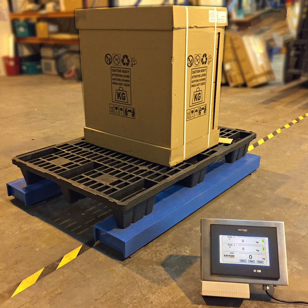


Weighing sensor is a kind of mass (weight) measurement method that converts mass (weight) into electricity through the stressed structure. The output electric quantity signal and the input quality (weight) signal have a single value linear correspondence; It has the required accuracy and high sensitivity; It has good frequency response characteristics and less inertia; Little influence on the state of the weighed object; Able to work in poor environmental conditions; Good stability, reliability and long service life.

 020-34563445
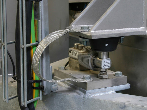
The weighing detection module is a sensor that utilizes the physical properties of a certain material or component related to temperature to convert temperature changes into electrical changes. The commonly used explosion-proof weighing sensors in measurement are thermocouples and thermistors. Thermocouples convert temperature changes into potential changes, while thermistors convert temperature changes into resistance value changes. In addition, the weighing module based on junction transistors and integrated weighing sensors has also rapidly developed and been widely used. The weighing module adjusts the force consistency of the sensors to reduce the impact of the "static instability" problem of multi support balance on the scale platform, ensuring the stability of the scale platform support, and thus ensuring that the center of gravity of the scale platform does not shift, achieving the accuracy and relevant measurement performance requirements of the scale. The weighing module has undergone various compensations during manufacturing, including output sensitivity compensation. The weighing sensor has a protection level of IP68 and can function in various harsh environments. The spherical connector always maintains the vertical weighing state of the module, preventing equipment from overturning. It is easy to install, fast, and easy to maintain, saving downtime for maintenance.
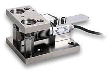
The weighing module adopts a weighing sensor, an upper pressure head, and a base. The lower end of the base is fixed with a lower connecting plate, which is fixed with an inverted U-shaped part that can limit the forward, backward, left, and right 360 degree swing of the weighing sensor. The center position of the upper end surface of the inverted U-shaped part is provided with a square hole, and the upper end of the weighing sensor is formed with a square block structure with four edges that matches the square hole. The lower end of the weighing sensor is set on the base, and the upper end passes through the square hole of the inverted U-shaped part and presses against the upper pressure head. A protective sealing ring is installed at the square hole of the inverted U-shaped part. The inverted U-shaped part of the weighing module is formed by integral stamping, and the lower end of the inverted U-shaped part is fixed to the left and right sides of the lower connecting plate by welding. The main body of the protective sealing ring of the weighing sensor is square, and a U-shaped groove is opened on the outer surface of the protective sealing ring to fit the square hole wall of the inverted U-shaped part.
The middle of the weighing module is cylindrical, and the upper end of the weighing sensor is a reduced diameter upper bearing end. The middle of the upper bearing end is convex with a square block structure that matches the square hole. The upper pressure head adopts a countersunk convex spherical structure, and the upper bearing end passes through the square hole of the inverted U-shaped part and is in contact with the groove on the lower end face of the upper pressure head. The middle square block structure of the upper bearing end is fitted with a protective sealing ring. The lower end of the weighing sensor is the lower bearing end that matches the base. The middle of the lower connecting plate is concave with a positioning groove for the base to be inserted. The lower end of the base is fixed to the lower connecting plate through screws in the positioning groove. The upper end of the base extends from the upper end surface of the lower connecting plate, and the lower end of the lower bearing end is provided with a positioning groove for the upper end surface of the base to be inserted. The depth of the positioning groove is smaller than the height of the upper end of the base. The top surface of the positioning groove is formed as an arc-shaped convex surface that is in contact with the upper end surface of the base. The diameter of the lower bearing end is consistent with the central cylinder of the weighing sensor, and a circular groove is opened between the lower bearing end and the central cylinder. The lower connecting plate is a square plate, the base is circular, the positioning groove in the middle of the lower connecting plate is a circular groove, and the positioning groove on the lower end surface of the lower bearing end is a circular groove. There are weight reducing hollow parts in the middle of the left and right sides of the inverted U-shaped part, and the upper end surface of the inverted U-shaped part is a horizontal circular plane. The left and right sides of the inverted U-shaped part have a structure with a wide middle and narrow upper and lower parts.
technical indicators
Rated capacity: 20kg, 50kg, 100kg, 200kg, 300kg
Sensitivity: mV/V 2 ± 0.002
Non repeatability:% R.O. ≤ 0.01
Lag:% R.O. ≤± 0.02
Nonlinear:% R.O. ≤± 0.02
Creep (30 minutes):% R.O. ≤± 0.02
Zero point output:% R.O. ≤± 1
Temperature compensation range: ℃ -10 to+40
Working temperature range: ℃ -20~+65
Sensitivity temperature coefficient:% load/℃ ≤± 0.002
Zero temperature coefficient:% R.O./℃ ≤± 0.002
Input impedance: Ω 387 ± 4
Output impedance: Ω 350 ± 1
Insulation resistance: M Ω 5000 (DC 50V)
Suggested excitation voltage: 5-15V (DC/AC)
Maximum excitation voltage: 20V (DC/AC)
Safe overload:% R.C. 150
Extreme overload:% R.C. 300
Protection level: IP68
Cable length: 3m


