









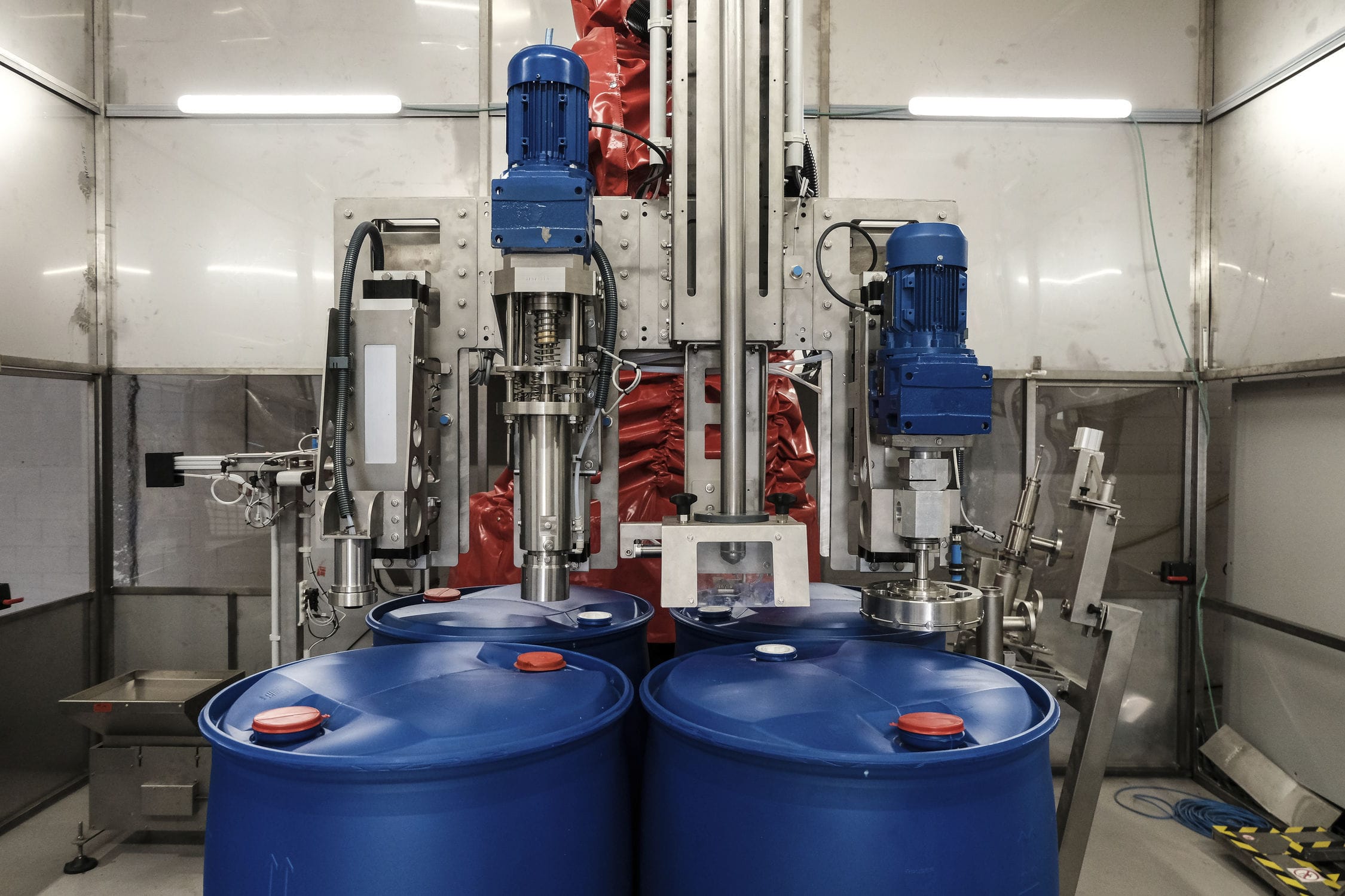
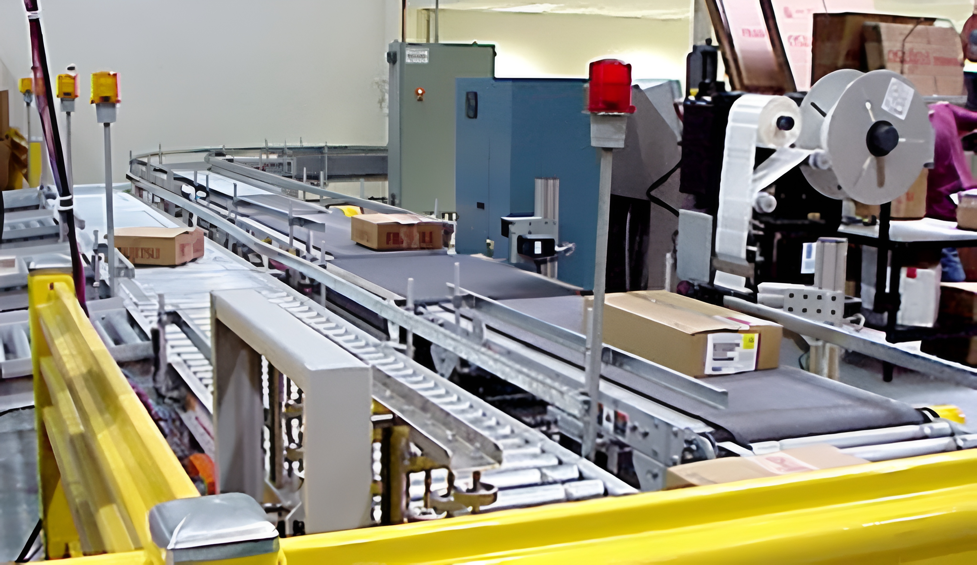
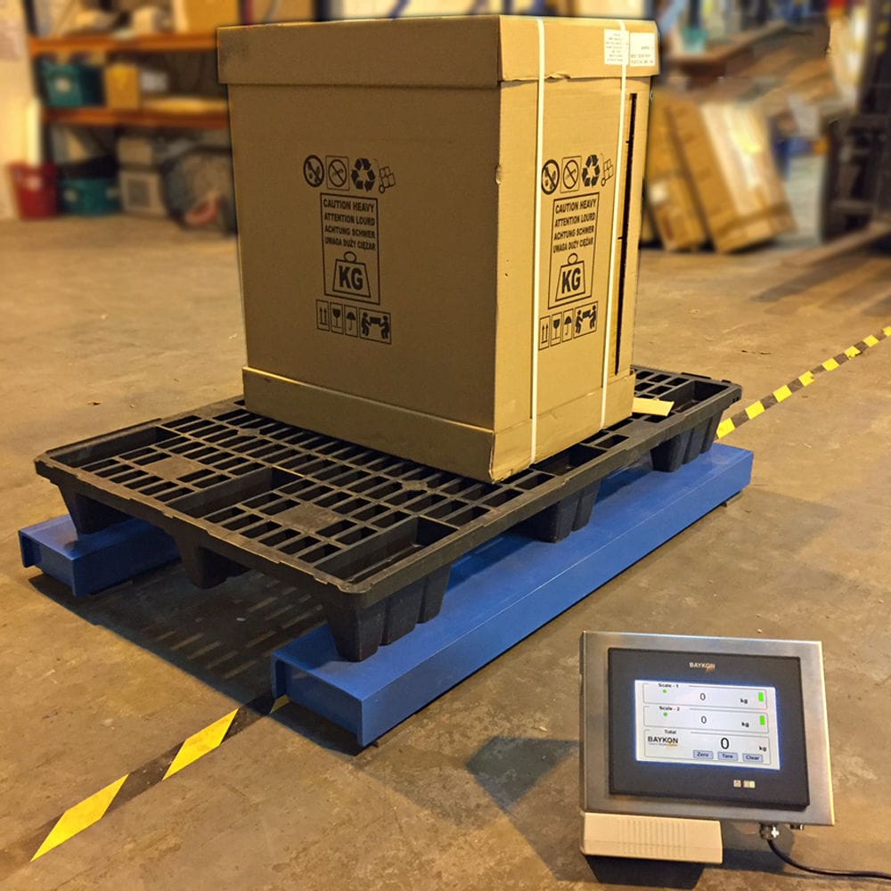


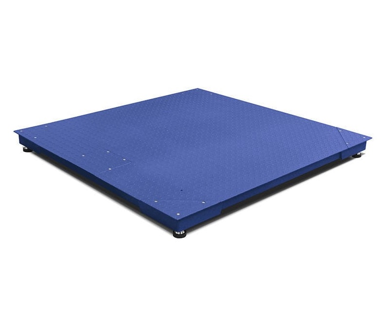
Digital Explosion-proof weighbridge consists of three basic units: weighing platform, load cell, and weighing instrument; the load cell part includes weighing instrument, weighing platform and signal cable. It adopts RS485 interface to communicate with digital load cell, and it can be adjusted manually/automatically for bias load (four-corner adjustment), address and read data of single sensor automatically, and modify the sensor number on the spot automatically. It can realize the processing of data, such as: display, calibration, sending, storage, printing and other functions.

 020-34563445
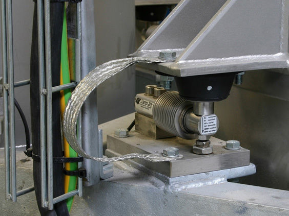
The explosion-proof Electronic scale is composed of a concrete base, a load-bearing plate, a weighing sensor and a load-bearing base. A slot is provided on the concrete base, and the load-bearing plate, the weighing sensor and the load-bearing base are all installed in the slot. The load-bearing base is installed at the bottom of the slot, and the weighing sensor is installed between the load-bearing base and the load-bearing plate through a bolt assembly. The bottom of the slot of the concrete base is provided with a drainage slope, and the bottom of the slot of the concrete base also has a drainage groove. The bottom of the drainage slope is connected to the drainage groove, and the drainage groove is inclined and sets in a way that it discharges the water accumulated in the slot body to the concrete base. The explosion-proof scale is installed with limit plates on the left and right side walls of the concrete base. The left and right side walls of the load-bearing plate are equipped with buffer devices. The buffer device includes a regulating bolt and a buffer block. The regulating bolt is threadedly connected to the left and right side walls of the load-bearing plate, and the end of the regulating bolt close to the limit plate is equipped with a buffer block. The spacing between the buffer block and the limit plate is smaller than the minimum spacing between the load-bearing plate and the limit plate. An additional reinforcing plate is installed on the outer side wall of the limit plate. A pull bolt is buried on the rear side wall of the concrete base, and the load-bearing base close to the pull bolt is fixedly connected to the pull bolt. The front and rear ends of the load-bearing plate are provided with installation slots, and the top of the installation slots is equipped with a first cover plate that covers the installation slots. The weighing sensor is installed through a bolt assembly on the left and right sides of the bottom of the installation slots. The left and right ends of the front and rear sides of the concrete base's front side wall are provided with forwardly protruding grooves, and the left and right ends of the rear side wall of the concrete base are provided with backwardly protruding grooves. The top of the grooves is covered by a second cover plate. The load-bearing plate is equipped with diagonal lifting rings. The drainage groove is located in the middle of the slot body, and the ends of the drainage slope are higher than the middle height of the drainage slope, and the rear end of the drainage groove is higher than the front end of the drainage groove.
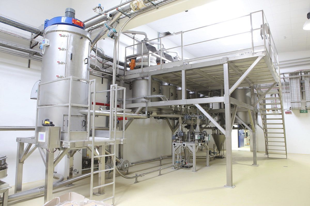
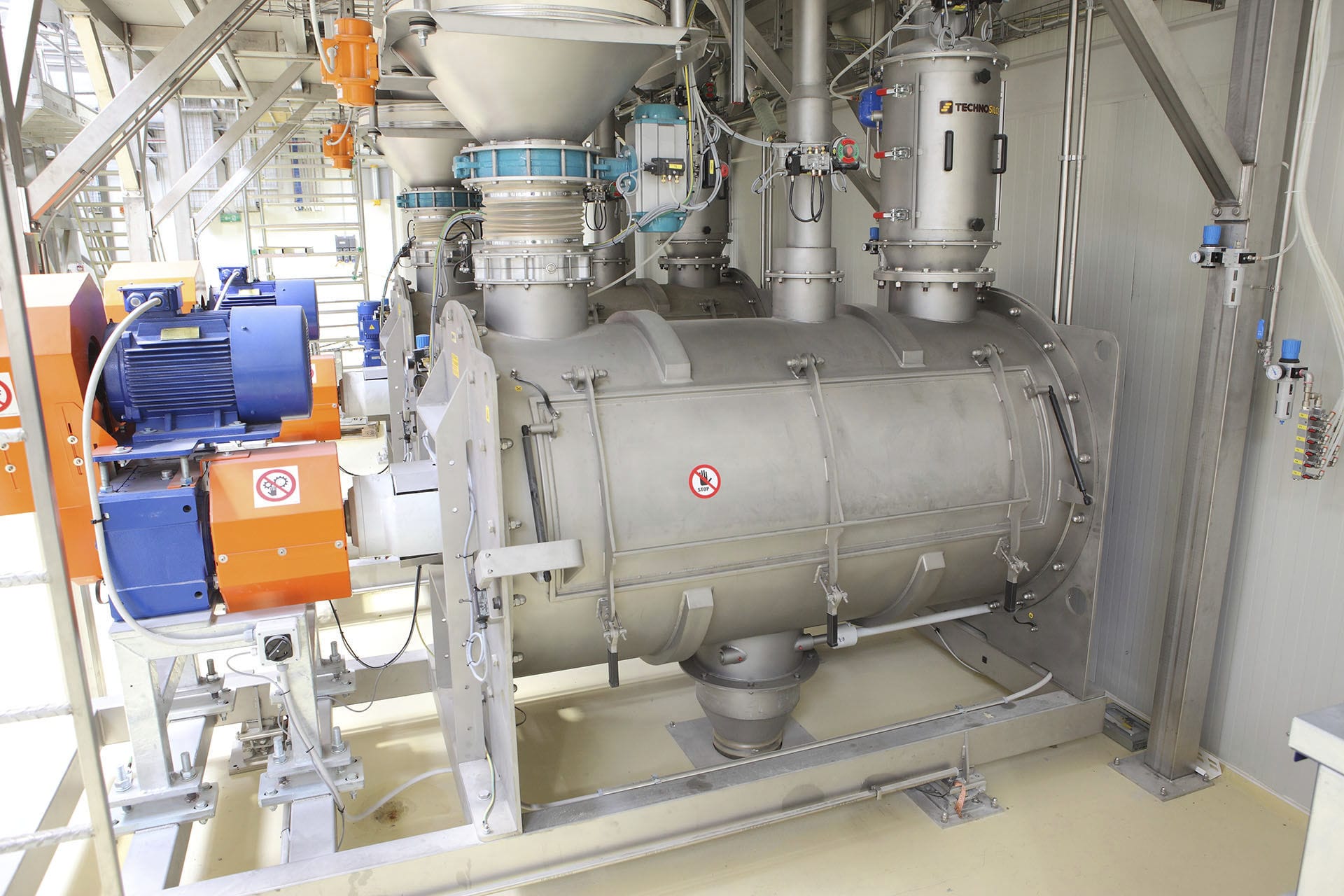
The explosion-proof digital scale system is composed of three basic units: the scale platform, the weighing sensor, and the weighing instrument. The weighing sensor part includes the weighing instrument, the scale platform, and the signal cable. It communicates with the digital weighing sensor through the RS485 interface and can perform manual/automatic load imbalance adjustment (adjustment at four corners), automatically address and read data for each sensor, and automatically modify the sensor number on site. It can also process data, such as display, calibration, sending, storage, and printing functions. The explosion-proof scale mainly consists of the weighing sensor, the weighing instrument, the programmable controller (PLC), the frequency converter, the industrial computer, and the printer. During the dynamic weighing process, it receives the weight signal from the scale. When the weight of the material in the hopper reaches the set value, it outputs an I/O quantitative signal to the PLC. The PLC collects the quantitative output signal from the weighing instrument and controls the output frequency of each frequency converter through the PLC, thereby controlling the coarse and fine feeding amount of the corresponding vibrating Feeder and the opening and closing of the material gate of each hopper. The industrial computer communicates with the weighing instrument through the RS232 interface and displays the weighing data of each scale on the monitoring screen. Users can adjust the formula on the weighing instrument panel or the operation interface of the industrial computer. During each batching process, using the powerful logical control function of the PLC, the vibrating feeder adopts sequential and synchronous working modes according to a certain logic, and the weighing hopper also works simultaneously, saving time and cost.
The electronic scale converts the analog electrical signals from the weighing module into digital signals or pulse signals. The digital sensor, digital junction box or digital scale can obtain the mass value of the weighed object through the sensitivity (mv/v) value of the sensor. Through the conversion of sensitivity, the force value (or mass value) can be accurately transformed into the corresponding electrical quantity value. Measuring this electrical quantity value allows one to obtain the measured force value. The most fundamental traceability device is the standard force source, and there is no need to trace back through standard weights. In contrast, the display of the analog scale, before being calibrated with standard weights, outputs a quantity without physical meaning. The measurement cannot determine the force value (or mass value) applied to the sensor connected to it. Due to the characteristics of the digital system, the force value (or mass value) can be measured without the need for weight calibration. The main essential difference between the digital system and the traditional analog scale lies in this. The concept of the redefined scale has introduced a deeper and more novel understanding of digital scales. This characteristic lays the foundation for the weight-free calibration of digital scales and this performance is more prominent in the industrial field.
Digital scales can individually address each weighing sensor within the system, enabling monitoring, fault identification for each sensor, and the ability to process the weighing information from each sensor separately. This significantly enhances the control and flexibility of the scale. Unlike traditional analog systems, in a large weighing instrument composed of multiple weighing sensors, these sensors are used in parallel. The characteristics of each individual weighing module cannot be distinguished, and when adjusting the uniformity of the force applied to each weighing sensor, there will be mutual influence. This requires repeated adjustments to achieve satisfactory results, and it also disrupts the original measurement characteristics of each weighing sensor. Digital electronic scales can directly process the raw weighing data provided by each weighing module. Each sensor can provide a resolution higher than 20 bits, equivalent to 1,000,000 counts. A system with four weighing sensors can provide 4x1,000,000 counts for analysis. For the Batching system, such high resolution is more beneficial for adding small amounts of materials. Since digital scales first analyze and process the raw signals, it is possible to detect whether the output of the weighing sensors exceeds the predetermined range and whether there are errors before resulting in incorrect weighing results.
The electronic scale incorporates a digital converter, digital circuits and microprocessors into the sensor housing. However, it can perform so-called digital compensation for the sensor's linearity, lag, creep, zero point and range's temperature effects. It can also store relevant data and parameters of the sensor and accept instructions through a dedicated display. It outputs digital signals encoded in ASCII format. It provides RS485 or RS485 interfaces. By inputting the sensitivity values of the four input channels of the connected sensors through the keyboard into the digital junction box, it can be used to measure the mass value. It has the function of addressing individual sensors connected and can store relevant parameters. Like the digital weighing sensor, it can be monitored through a dedicated display or PC to form the required weighing instrument. The difference from the digital weighing module is that it cannot compensate for the measurement characteristics of the sensor (except for linearity).


