











Mobile Explosion-proof electronic scale refers to the static input signal, the output and the input quantity of the mutual relationship between. That is, the static characteristics of the sensor can be used as a time-varying algebraic equations, or to the input as the horizontal coordinates of the corresponding output as the vertical coordinates of the characteristics of the curve drawn to describe. The main parameters that characterize the static characteristics of the sensor are: linearity, sensitivity, hysteresis, repeatability, drift, etc.



 020-34563445
The mobile explosion-proof Electronic scale has powerful functions for handling the packaging process, setting the target weight of any packaging, automatically removing tare weight, automatically correcting errors, and controlling the feeding execution mechanism with multiple speed outputs. It also has the function of prohibiting sampling time setting to eliminate the influence of vibration and material flushing on measurement accuracy, and has functions such as out of tolerance output alarm. It is equipped with multiple communication interfaces for communication with the upper computer and corresponding operating software, which can be easily connected to the central control system of the complete production line. Through frequency conversion (servo) control technology, it runs within a rigorous logic program of a programmable logic controller (PLC), making the operation process intelligent, reliable, and stable; Make manual operation very simple. Explosion proof electronic scales integrate computer technology, automatic control, communication technology, and weighing technology. They have complete control functions, centralized display and operation, convenient data processing, simple installation and maintenance, and easy system expansion. Structurally solving the problem of "centralized danger" in computer centralized control systems, achieving "centralized management and dispersed danger", supporting multiple communication protocols for data collection and process control, providing users with multiple device supports, rich and colorful dynamic images, and powerful system functions, making it easy to operate, with strong scalability, easier to integrate with other systems, and more effectively protecting users' investments.
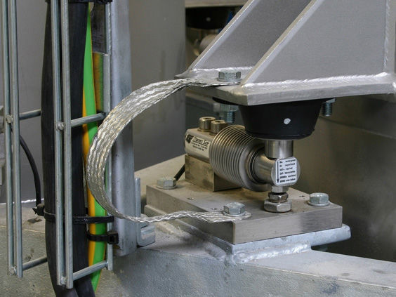
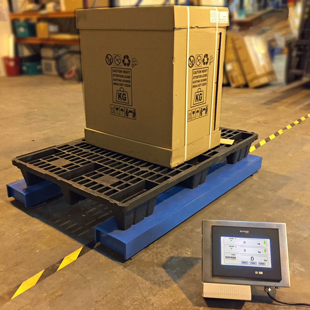
The weighing scale adopts a bottom frame, a weighing body, and a weighing sensor. The weighing sensor is located at the four corner ends of the top surface of the bottom frame and supports the weighing body. The four corner ends of the top surface of the bottom frame are respectively equipped with symmetrical weight sensors. The bottom frame includes a bottom plate and a channel steel. The two ends of the channel steel are connected to the ends of the bottom plate to enclose a rectangular frame. The weighing sensor and the corner guard are both installed on the bottom plate. The weighing sensor is located on the inner side of the corner guard, and the outer side of the channel steel forms an upward folding edge. The two ends of the weighbridge corner guard are respectively provided with threaded holes, and the two ends of the folded edge are respectively provided with corresponding threaded holes and installed on the bottom frame. The inner surfaces of both ends of the corner guard are respectively equipped with mounting plates, on which sliding clips are installed. The folded end face is provided with corresponding slots for the clips. The two ends of the corner guard are respectively equipped with driving components for inserting the driving clips into the slots.
The front and rear sides of the weighbridge frame are respectively equipped with pull rod grooves, and telescopic pull rods are installed inside the pull rod grooves. The telescopic pull rods can be made of square tubes. One end of the telescopic pull rods on the front and rear sides of the scale frame is respectively equipped with a handle 4 and a wheel set. The upper surface of the telescopic pull rod is equipped with a clamp head that is compatible with the pull rod groove. When the telescopic pull rod extends outward to the maximum stroke, the clamp head on it is placed at the groove outside the pull rod groove. The wheel set includes a wheel shaft and two wheels. The wheel shaft is fixedly installed on the extended end of the telescopic pull rod on the back of the scale frame, and the two wheels are installed at both ends of the wheel shaft through bearings and nuts. Pull out the handles and wheels of the telescopic pull rods on the front and rear sides of the scale frame until the maximum stroke is reached. At this point, place the card heads on the surface of the telescopic pull rods on the front and rear sides of the scale frame at the corresponding groove outside the pull rod groove. Then lift the handles by hand to tilt the scale body. Due to the weight of the scale body itself, the entire scale body is pressed against the surface of the telescopic pull rods on both sides, causing the pull rod grooves on both sides of the scale frame to be stuck by the card heads. At this point, the push-pull platform scale can be moved to the designated location. Finally, place the scale body horizontally, release the pull rod groove, and retract the telescopic pull rods on both sides of the scale frame to reset the handle and wheels, saving a lot of space and making movement convenient and fast.


