









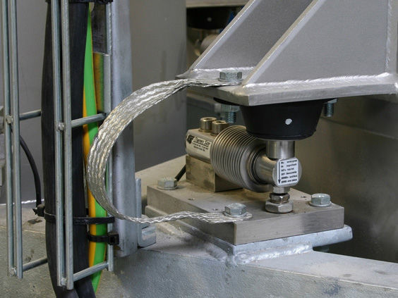


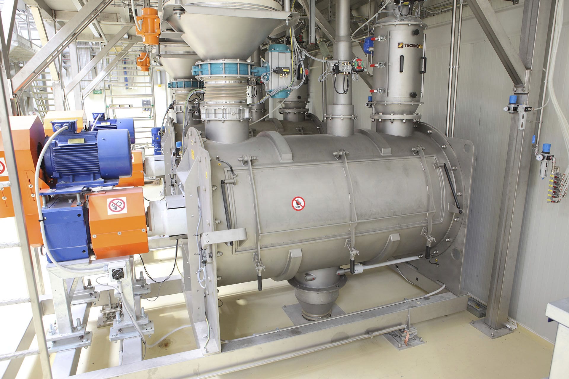

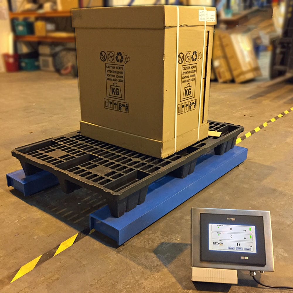


The load-bearing and force-transmitting mechanism platform of the ground scale is grounded and connected to the grounding device through equipotential connection. The grounding device of the entire ground scale system is laid 1.5 meters away from the exterior wall of the scale room and buried at a depth of 2.5 meters. The specification is 50x50x hot-dip galvanized angle steel, with a spacing of 5 meters. The horizontal grounding device is a 16-round horizontal grounding electrode. In fact, only two vertical grounding steel bars are exposed on the ground surface and serve the purpose of grounding.

 020-34563445
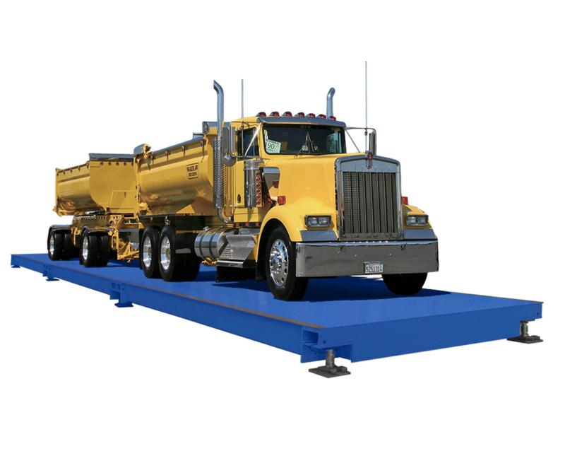
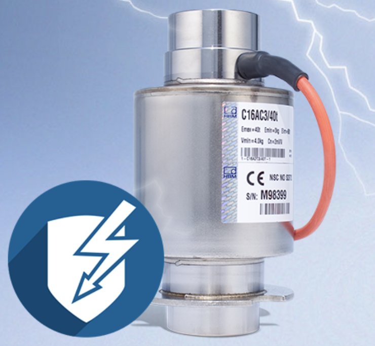
The lightning-proof weighing platform is composed of three main components: the load-bearing force transmission mechanism, the high-precision weighing sensor of the scale body, and the weighing instrument. With these components, the basic weighing function can be accomplished. According to the user's requirements, a printer, a large-screen display, and a computer management system can also be selected for higher-level data management and processing requirements. Due to the characteristics of the electronic weighing platform and the presence of large metal components in the system, the electronic weighing platform is prone to direct lightning strikes. The load-bearing platform, the load-bearing and force-transmitting mechanism of the electronic weighing platform are all large metal objects, while their stress sensing components are sensitive electronic devices. The signal transmission system of the electronic weighing platform is composed of sensitive electronic devices. It is very likely to be damaged by transient overvoltages caused by resistance or capacitance coupling. When lightning induction voltage is generated on the metal scale platform, the elastic body of the weighing sensor is electrically connected and will induce a high voltage, which will break through the strain gauge and its output circuit of the sensor, thereby damaging the equipment. The electronic weighing platform is repeatedly struck by lightning, which is likely to cause damage to the weighing computer motherboard, controller integrated chip, and weighing sensor, resulting in the paralysis of the electronic weighing platform system and affecting normal production and business activities. The load-bearing and force-transmitting platform of the weighing platform adopts grounding and is connected to the grounding device in equipotential. The grounding device of the entire weighing platform system is laid 1.5 meters away from the exterior wall of the weighing platform room and buried 2.5 meters deep, with a specification of 50x50x hot-dip galvanized angle steel, and the spacing is 5 meters. The horizontal grounding device is a 16-round middle column. In fact, only two vertical grounding steel bars are exposed on the ground surface and play the role of grounding.
The low-voltage power distribution wiring situation: The power lines are suspended and led out to the exterior wall of the weighbridge room, where they are introduced into the main distribution box through PVC pipes and then distributed to the distribution box, and finally to the power socket in front of the weighbridge control host. The front end is a socket-type SPD, which has been tested and found that its startup voltage is nearly 2000V. This SPD cannot protect the sensitive electronic equipment at the rear end. The power supply system is TN-S. The signal transmission interface of the weighbridge sensor is a 9-pin RS232 signal line. There are two surveillance cameras in the weighbridge room. The electronic weighbridge adopts SPD lightning protection measures to prevent direct lightning strikes. Lightning current invading the system is likely to enter directly through the lines or through the electromagnetic pulse radiation induced by lightning induction and damage the equipment.
When lightning electromagnetic pulse (LEMP) protection is required, and when the building does not have a direct lightning protection device installed, and the LPS is not within the protection range of other buildings or objects, measures to prevent direct lightning strikes should be taken according to the third category of lightning protection buildings. In cases where shielding is considered, lightning protection nets should be used. The lightning protection design for the electronic weighing scale system should be carried out according to the third category of lightning protection buildings. Lightning arresters should be installed on the roof of the weighing room and the duty room. The lightning arresters should use lightning arrest grid with a grid size not greater than 24x16m for direct lightning protection. Lightning arrest strips should be laid along the corners and eaves of the building, and should be set every not greater than 25m. The actual distance is 24m. The down conductors should be laid along the perimeter of the building and be evenly distributed. The down conductors should be connected to the grounding device using breakaway clips. The materials of the lightning arrest strips, lightning arrest nets and down conductors should be Φ12 hot-dip galvanized round steel. The weighing scale platform exposed outside should be placed within the direct lightning protection range. Since the distance between the weighing room and the scale platform is relatively close, the direct lightning protection measures of the weighing room, in addition to being within the safety protection range of itself, can also protect the entire scale platform. If the scale platform is not within the safety protection range of the building, a direct lightning protection device should be designed to protect the entire scale platform, which should be within the safety protection range.
A circular artificial grounding device was laid 1 meter behind the scale room and 1 meter away from the exterior wall as the common grounding device for the system, for lightning protection against direct strikes, equipment grounding, SPD grounding, scale platform grounding, sensor elastic body grounding, video and signal line shielding grounding, etc. All of these were connected to the common grounding device. The horizontal grounding body used was 40x4 hot-dip galvanized flat iron, and the vertical grounding electrodes used were 50x5x1500 hot-dip galvanized angle steel. One was laid every 5 meters along the horizontal grounding electrode, with a laying depth of 2.5 meters. After completion, the measured grounding resistance of this grounding device was no more than 4 ohms, basically meeting the requirements for grounding of electrical equipment. If the grounding resistance does not meet the design requirements, additional artificial grounding devices should be added. According to incomplete statistics, lightning overvoltage is introduced from power lines and communication lines. To prevent lightning waves from invading along the power lines and ensure the safety of equipment, the AC power lines, video signal lines, and control signal lines outdoors of the scale system are laid with metal shielding layer cables and buried in pipes, with a burial length of 25 meters. The shielding layer and the ends of the pipes are connected to the lightning protection grounding device at the same potential. At the main distribution cabinet where the low-voltage power lines are introduced, the distribution box in the scale room, and the front end of the dedicated sockets for sensitive equipment, appropriate power SPDs are installed. At the entrances and exits of the video transmission lines, signal control lines, etc., of the scale room, appropriate signal SPDs are installed at the entrances and exits. The selection and installation of SPDs should comply with the relevant requirements of GB50057 and GB50343.


