


The weighing mixed system adjusts the speed of the reducer motor by PID algorithm according to the comparison results, so as to achieve the purpose of adjusting the feeding speed of the rotor pump driven by the motor, so that the actual flow is equal to the set flow, so as to ensure the battering accuracy. When the weight of the hopper is detected and the skin is automatically removed, the stepper motor accelerates evenly to the highest speed value to drive the rotor pump to fast feeding. When the feed is expected to fast feeding, the stepper motor runs at a uniform low speed, thus driving the rotor pump to slow feeding. When the feed is expected to slow feeding, the stepper motor is controlled to advance at a very low pulse. Drive motor point feeding, until the set value is expected, the second automatic weighing and fractional control begins after unloading.

 020-34563445
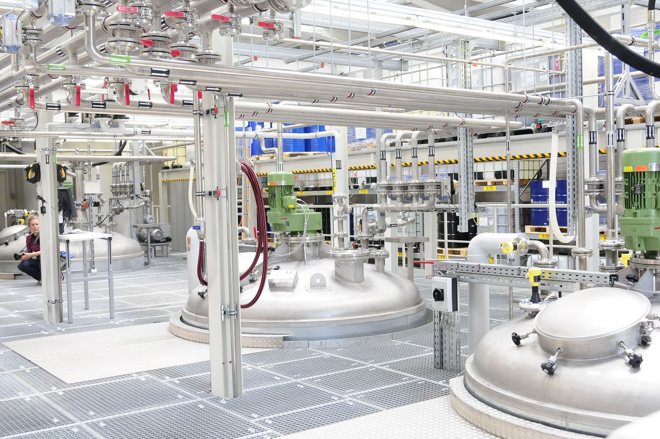
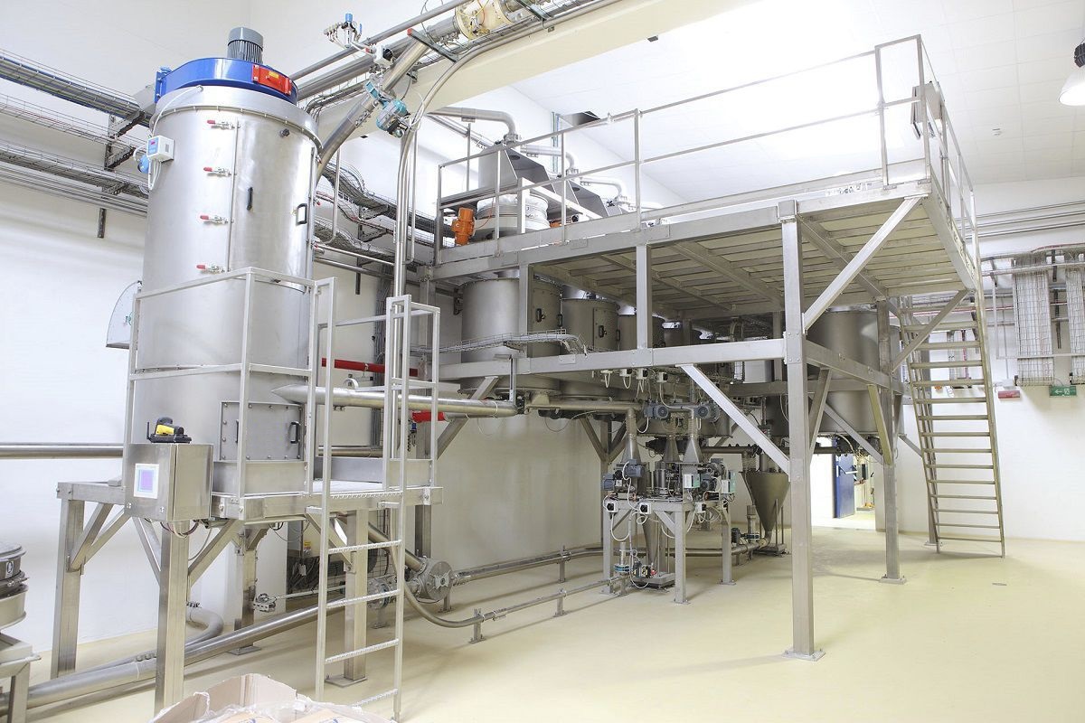
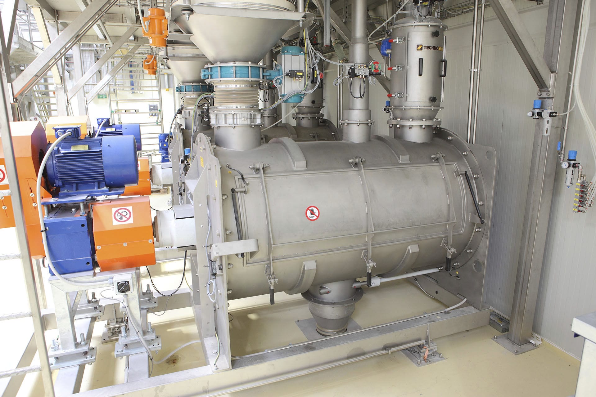
Batching control system is a kind of production equipment used for processing different powders or liquid materials in a certain proportion automatically and precisely. It is usually composed of Weighing system, weighing control instrument, PLC system and host computer. The batching control system includes raw material storage body, conveying body, weighing batching body, dust removal body, material mixture and so on. According to the characteristics of the industry, production process requirements, specific material characteristics, reasonable selection of "incremental" or "reduction" weighing methods, with a single bucket single material, single bucket multi-material, multi-bucket multi-material and other working modes.
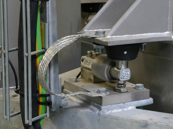
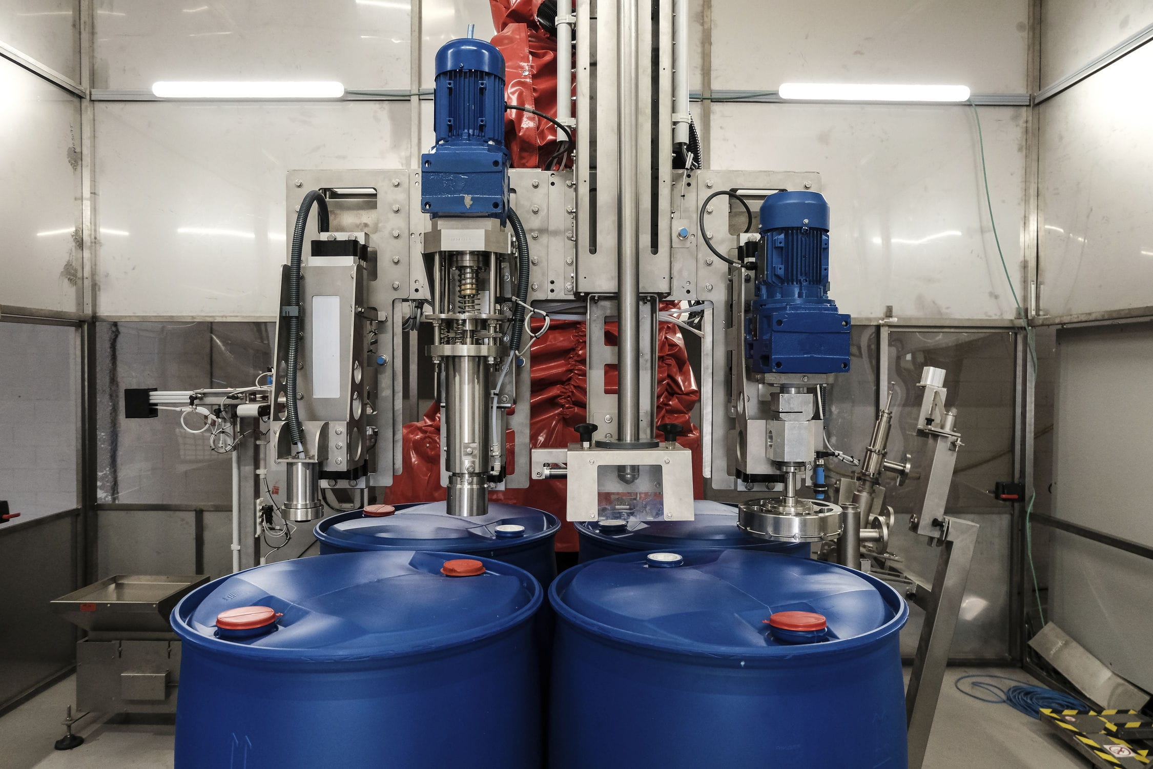
The feeding system is composed of two parts: the main circuit and the PLC system. Its working principle is that each component is pumped into the metering barrel by the rubber valve and injected into the mixing tank. Its own weight acts on the weighing module. When the weighing module is stressed, its 0-10V output voltage signal is sent to A/D converter (weighing instrument), converted into a digital signal and sent to the PLC for processing. Ingredient control values for various components have been entered into the PLC via HMI. The PLC sends the detected weight value to the HMI for display and comparison with the given value. When the detection value is equal to (or greater than) the given value, the control interface outputs the control signal to stop the pneumatic valve dispensing and complete the addition of the first raw material. Then add the second raw material, and add the other ingredients in turn. After all the ingredients are completed, the PLC sends a signal to stir, and the stirring time is set by the HMI and sent to the PLC. After stirring, the liquid is automatically placed into the core (table) layer tank.
According to the control function requirements of the feeding system, it is necessary to carry out various logic, sequence and process control of the equipment, including manual automatic control of the equipment, various alarm input, output and signal feedback. This requires more PLC input and output points. Among them, the input signals controlled by PLC include the start and stop button on the operating platform, the upper and lower limits of the liquid level switch, the signal that the pneumatic valve is closed in place, the overload signal of each motor, etc. (a total of 55 points); PLC controlled output signals include: each motor and solenoid valve operating status indication, discharge valve intermediate relay AC contactor and other contacts. During the operation of the system, the user needs to enter the formula of the core layer and the surface layer, the mixing tank, the limit control value of the core layer and the surface tank, the feeding time and other related information, and print the historical curve of the liquid consumption of the core layer and the surface layer per minute. According to these requirements, the PLC is connected to the Human machine interface (HMI) via RS-485, and the HMI is connected to the micro printer via a USB interface.
The field switch signal enters directly into the PLC input port, while the weight signal of the mixing tank, core tank and table fabric tank enters the PLC from the analog acquisition module. For the control signal output by split PLC, the 24V signal is divided into a group, and the common positive electrode is directly connected to the actuator through the PLC; The 220V feed pump and agitator are divided into a group, also controlled directly by the PLC. The HMI is a two-way communication bridge between the operator and the machine. Operators can input data according to the prompts on the screen, observe the parameter changes of the process, monitor the production process in real time, achieve visual operation, and reduce operation errors. The HMI is also responsible for downloading the liquid mixing process parameter values to the PLC and printing out the real-time data at the end of the process.


