









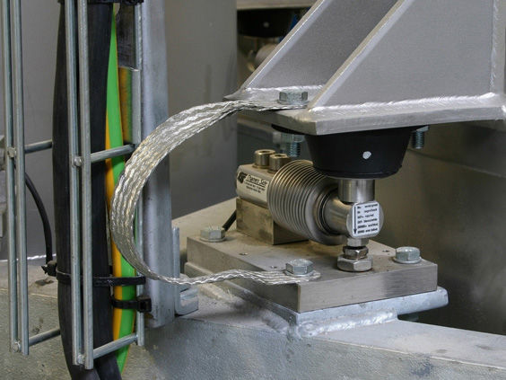


The underground track scale transmits the weight from the scale body to eight weighing sensors. When a vehicle enters the track scale, each section of the vehicle and its cargo will convert the weight they bear proportionally into an electrical signal and input it into the weighing controller for amplification, filtering and A conversion. The converted digital signal, after being processed by the CPU, is displayed on the display window of the weighing display controller. If a microcomputer and a printer are connected to the system, the net weight, gross weight, and tare weight of the entire train (or individual section) can be statistically processed and the results can be printed out.

 020-34563445
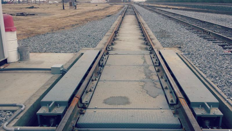
The track scale is a large-scale weighing equipment installed on railway tracks, used to weigh the bulk cargo loaded on railway wagons. The load-bearing mechanism of the track scale is the device that bears the weight of the weighed vehicles and the cargo they carry. It is also required to accurately transfer the weight to the weighing sensor. The load-bearing mechanism of the track scale generally consists of the guide rail line, the overall track bed, the scale body foundation, the scale body structure, and the weighing sensor and weighing instrument. The track scale body structure of the broken rail track scale generally consists of the scale beam system, the scale beam rail, the limit system, and the transition device. The transition device is an important component of the track scale body structure. The track scale transmits the weight to the eight weighing sensors through the scale body. When a vehicle enters the track scale, each section of the vehicle and its cargo will convert the weight it bears into an electrical signal proportionally and input it to the weighing controller for amplification, filtering, and A conversion. The converted digital signal, after being processed by the CPU, is displayed on the weighing display controller's display window. If the system is equipped with a microcomputer and a printer, it can statistically process the net weight, gross weight, and tare weight of the entire train (or a single section) and print the results. The scale adopts the internationally popular welded beam structure. The important components such as the main beam, limit device, connection plate, and platform plate are optimized for design, removing unnecessary partitions and rib plates. The overall structure strives for simplicity, practicality, reliability, aesthetics, and outstanding craftsmanship. The main beam is welded from high-quality steel plates into a box-shaped beam structure, which has sufficient strength and rigidity, and has good craftsmanship. It can be produced by automated welding methods, facilitating large-scale production. The weighing rails and anti-slip rails are fixed by the railway standard elastic bar pressing method, with constant pressure, and the steel rail anti-slip effect is good. The structure is novel and aesthetically pleasing, with high standardization, while effectively reducing costs. The transition system adopts a bridge-type transition device, which can ensure that the wheels pass smoothly over the track gap on the platform, eliminating the impact of the wheels on the scale body, and fully ensuring the measurement accuracy. The limit system includes the lateral pull rod limit system and the longitudinal impact limit system. The pull rods and the impact top are installed on the upper part of the main beam, effectively ensuring the stability of the scale body. Among them, the longitudinal impact steel ball limit system form is a patented technology of our company, effectively ensuring the accuracy and stability of the measurement.
To ensure that the curve requirements of the rails on the long-track surface track scale conform to the on-site dimensions after installation, the rails of the track scale should have the same curvature radius as the curve radius of the railway line. First, the curvature radius of the inner and outer rails should be calculated based on the rail spacing at the installation location of the track scale. If the rail spacing is small and the curvature radius of the curve is large, it can be approximately considered that the curvature radius of the inner and outer rails is the same, both equal to the curvature radius of the curve section. Secondly, a reference point should be determined on the main beam, and the relative size of each sink plate on the main beam should be calculated based on the curvature radius of the railway rail and the spacing between the two sink plate plates. In this case, the placement of the sink plates is convenient for the curvature radius of the rails, and the width of the main beam of the track scale is widened. When the rails are placed on the sink plates and fixed by the elastic bar, the curvature radius of the rails can be ensured. The scale ensures the safety operation of railway vehicles by the action of centrifugal force. When arranging the rails of the curve section on the railway line, the outer side (with the origin of the curvature radius as the inner side) of the rails is higher than the inner side rails to ensure a certain height difference between the two rails. When arranging the sink plates on the main beam, two height dimensions of the sink plates are designed, with the thick sink plates on the outer main beam and the thin ones on the inner main beam. Moreover, the height difference of these two sink plates is equal to the height difference between the inner and outer rails on the railway line. This ensures that the vehicle can smoothly enter the transition rail from the railway rail and then enter the weighing rail, ensuring the safety of vehicle operation. To meet the requirements of a few petroleum refining enterprises that do not have straight inbound and outbound factory and shunting lines with track circuits, a static track scale is adopted to measure the train vehicles. The main features of this system are high accuracy, good reliability, simple operation, strong adaptability, and the ability to measure ultra-long liquefied gas tank cars that comply with national railway operation standards. The track scale's function determines its high usage frequency and high safety requirements. Generally, faults are not allowed to affect the normal operation of the system. Once the system fails, it should be able to quickly identify the fault point and repair it to restore normal operation. To meet these requirements, reliability design for the track scale is necessary, laying the foundation for the product's reliability. From the structure and working principle of the track scale, it can be seen that the strength and stiffness of the mechanical scale body have a significant impact on the stability of the entire system. The failure of the mechanical structure will cause the entire system to collapse, while the failure of the sensor and weighing display controller will result in incorrect weighing results.
The structure of the track scale adopts a fixed mechanism composed of rail clamping brackets installed on the rails and Weighing modules installed on the sleepers through connecting accessories. After the new track weighing structure is assembled, the bottom surface of the rails does not directly contact the rail bed of the sleeper. The fixed mechanism can swing up and down when the rails are under pressure. The track weighing structure uses rail clamping brackets including the clamping seat and the bridge plate; the clamping seat is in the form of a square, and the clamping seat is provided with an inner groove and a connection hole, the size of the inner groove matches the concave edge of the cross-section of the rail; the bridge plate is in the form of a square strip, and the middle part of the bridge plate is provided with a hole for installing the weighing module; the rail clamping bracket is a single integral structure composed of two clamping seats welded or fixed by bolts on the left and right sides of the bridge plate; the connecting accessories include transition platform frame, adjustment pad plate, adjustment rubber pad, rail clamping bracket combination bolt, bridge plate connection combination bolt and sensor compression combination bolt; the front end of the transition platform frame is provided with an installation hole for connecting with the threaded spike on the sleeper bed, and the rear end has a threaded hole for installing the weighing module; the adjustment pad plate is in the form of a square sheet, and the middle part is provided with a center hole; the adjustment rubber pad is a rubber pad; the rail clamping bracket combination bolt, bridge plate connection combination bolt and weighing module compression combination bolt are all standard connection components. In the assembled state of the track scale, each measurement area needs to install a set of weighing modules on both the inner and outer sides of the rails on the same sleeper, during installation, the center line of the sleeper is used as the center, two rail clamping brackets are used to align and interlock the inner and outer sides of the rails on the lower edge of the rails, and the rail clamping bracket combination bolts are threaded through the connection holes and tightened to fix the rail clamping brackets on the rails; the adjustment rubber pad is placed on the sleeper bed surface through the threaded spike pad on the sleeper bed; the adjustment pad plate is placed on the adjustment rubber pad through the center hole and installed on the adjustment rubber pad; the front end of the transition platform frame is installed on the adjustment pad plate through the installation hole on the sleeper bed and tightened with a nut to fix it to the sleeper; the rear end is placed on the concrete surface of the sleeper end; the rail clamping bracket is convenient to be connected with the rail as a single moving body, and the transition platform frame and the sleeper form a basic body; the weighing module is placed on the installation platform composed of the transition platform frame and the bridge plate, one end of the weighing module is connected to the bridge plate through the bridge plate connection combination bolt, and the other end is connected to the rear end of the transition platform frame through the sensor compression combination bolt.


