


The flow explosion-proof scale automatically controls the motor speed by collecting pulse signals through PLC, and uses the number of pulses to control the total volume of the liquid. The touch screen is connected to the serial port of the weighing instrument via an RS232 communication cable, exchanging data in real time to complete functions such as parameter setting of the equipment, flow display, operation control, historical data storage, and alarm information preservation.

 020-34563445
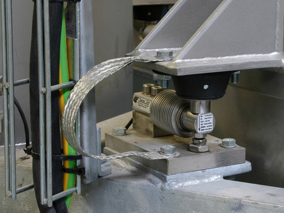
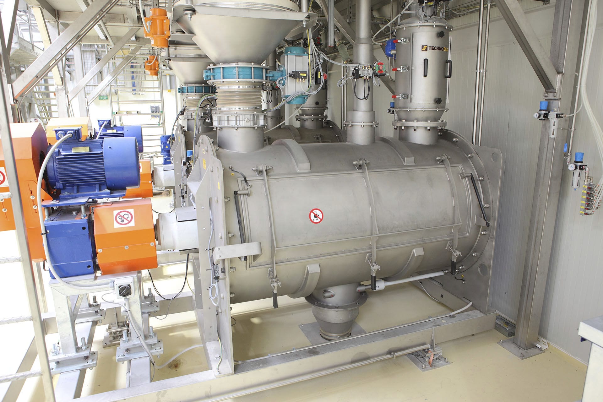
The flow explosion-proof weighing platform control system consists of a liquid storage tank, valves, centrifugal pumps, AC asynchronous motors, frequency converters, explosion-proof weighing platforms, etc. The weighing platform transmits the weight from the platform body to the weighing sensor, which then generates a force-electric effect, converting the weight of the object into an electrical signal that is proportional to the weight of the object being weighed. This signal is amplified by the amplification circuit, filtered, and then converted by the analog/digital (A/D) converter. The digital signal is sent to the CPU of the microprocessor for processing. The CPU continuously scans the keyboard and various function switches, making necessary judgments and analyses based on the input content of the keyboard and the status of various function switches. The weighing instrument then controls and measures the filling and discharge volume of the silo pipeline. According to the pulse signals collected by the PLC, the motor speed is adjusted automatically for automatic control. The total volume of the liquid is controlled by the number of pulses. The touch screen is connected to the serial port of the weighing instrument through an RS232 communication cable, exchanging data in real time to complete functions such as parameter setting, flow display, operation control, historical data storage, and alarm information preservation. The parameters are set through the friendly human-machine interface of the touch screen, and the instructions are sent to the PLC. The PLC can then control the operation of the entire buffer tank.
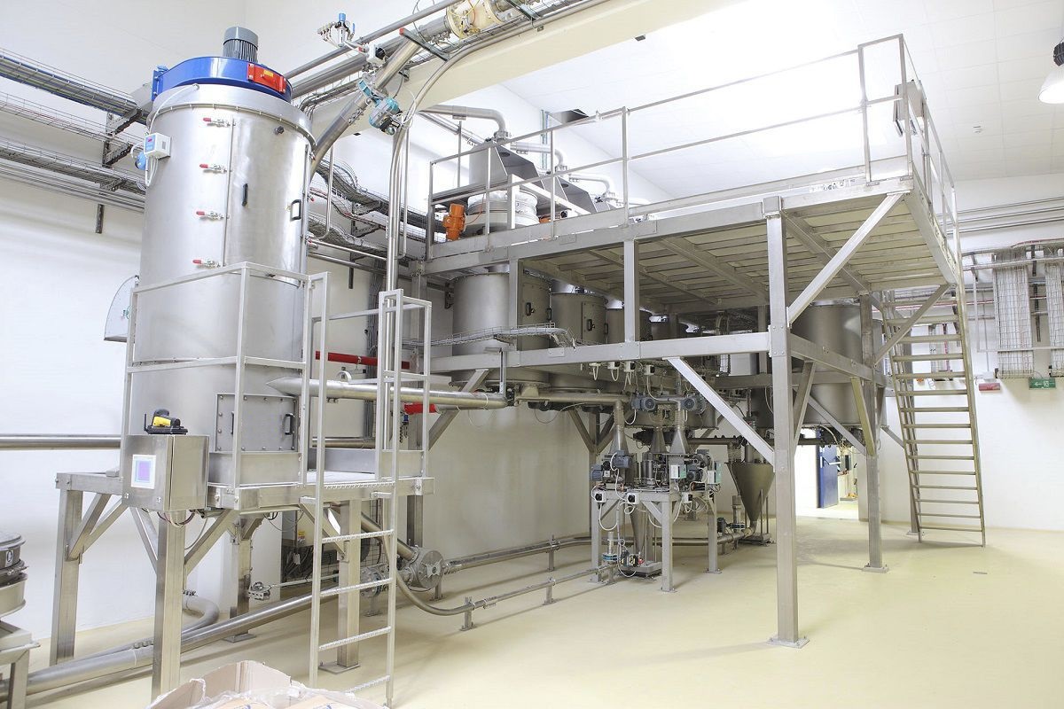
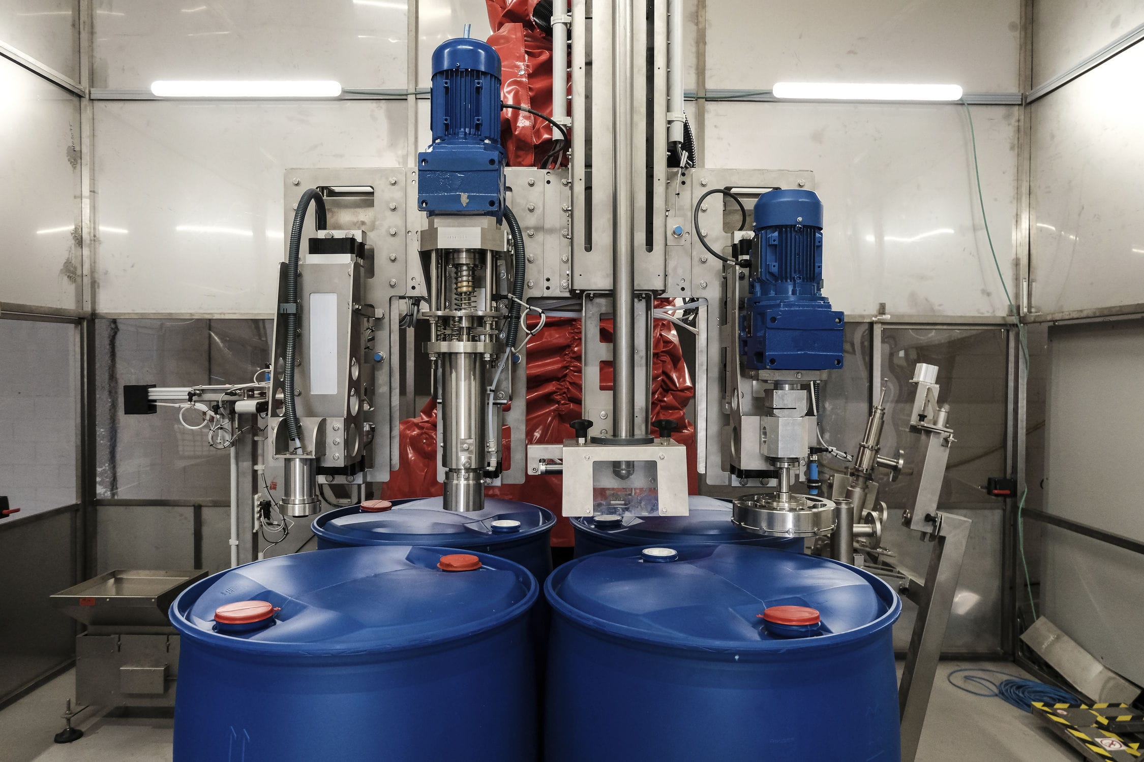
The intermediate buffer tank on the explosion-proof electronic weighing platform displays the weight of the raw materials. In the automatic PID control mode, the PLC first collects the actual liquid level of the buffer tank. After being calculated by the pre-written PLC internal program, a corresponding 4-20mA current signal is sent to the frequency converter through the analog output module. Then, through the PID control program of the frequency converter's internal calculation, a speed control signal is given to the frequency converter. The negative feedback of the explosion-proof weighing platform then controls the instantaneous flow of the pipeline. The PLC gives the set flow rate, and there is a deviation between the two in real-time measurement. PID regulation is used for the actual flow control. The speed of the pump is adjusted by the frequency converter, and the quantity is adjusted to be equal to the set value. The actual operating frequency of the frequency converter is sent as a 4-20mA current signal to the analog input module of the PLC through the program processing, and the output current is corrected by the internal program of the PLC to form a closed-loop control.
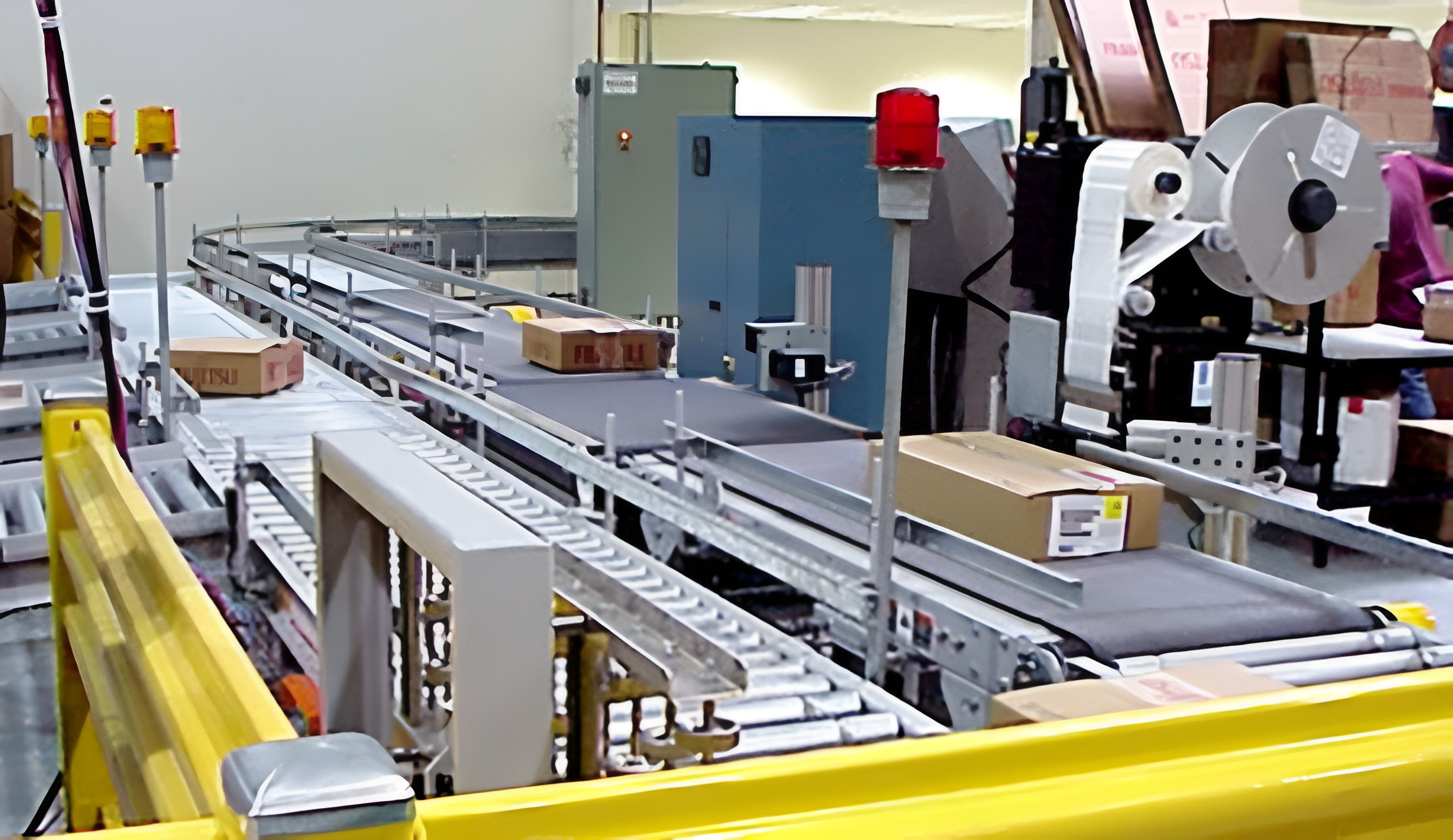
The explosion-proof Electronic scale combines all the remote signals of the centrifugal pump motors and valves on site in the PLC program. The automatic program can only be run when the lower computer issues a start command. The opening and closing control positions of the inlet and outlet valves of the centrifugal pump are set to ensure that each valve is fully open. After receiving all the open到位 signals of the valves, a delay of 3 seconds is applied, and the electronic scale controls the frequency converter of the centrifugal pump to start. At the same time, the frequency converter's setting frequency of the PLC is transmitted through the move instruction and processed by the program to be converted into a 4-20mA signal sent to the frequency converter of the centrifugal pump, which is the initial operating frequency of the frequency converter. This ensures that the centrifugal pump operates in the liquid content of the pipeline. The feedback value of the liquid content in the pipeline is converted into an analog 4-20mA signal and sent to the analog input module of the PLC through the PLC program. This signal is converted into an actual value by the internal program and compared with the set standard value in the program. The error is within ±1kg. Within this range, no adjustment is made to the frequency of the centrifugal pump frequency converter. When the liquid content in the pipeline exceeds the upper limit of the standard value, the frequency converter's speed will be rapidly increased, increasing the speed of the centrifugal pump motor. Since the speed of the motor is in a cubic relationship with the outlet flow of the pump, the outlet flow of the centrifugal pump will increase rapidly, which also increases the flow of the valve and the reaction intensity of the liquid in the pipeline. This can quickly reduce the liquid content in the pipeline to the standard value range. When the liquid content in the pipeline is lower than the lower limit of the standard value, the frequency of the centrifugal pump's frequency converter gradually decreases, and the outlet flow of the centrifugal pump gradually reduces. This means that the flow of the valve also gradually decreases, reducing the reaction intensity between the liquid in the valve and the liquid in the pipeline. Thus, the liquid content in the pipeline is maintained within the standard value error range. Through repeated program operation and adjustment, a relative balance is achieved, and the liquid content in the pipeline is stabilized within the standard value error range.


