









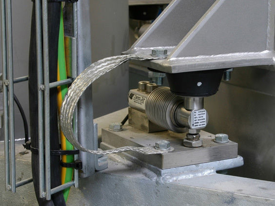
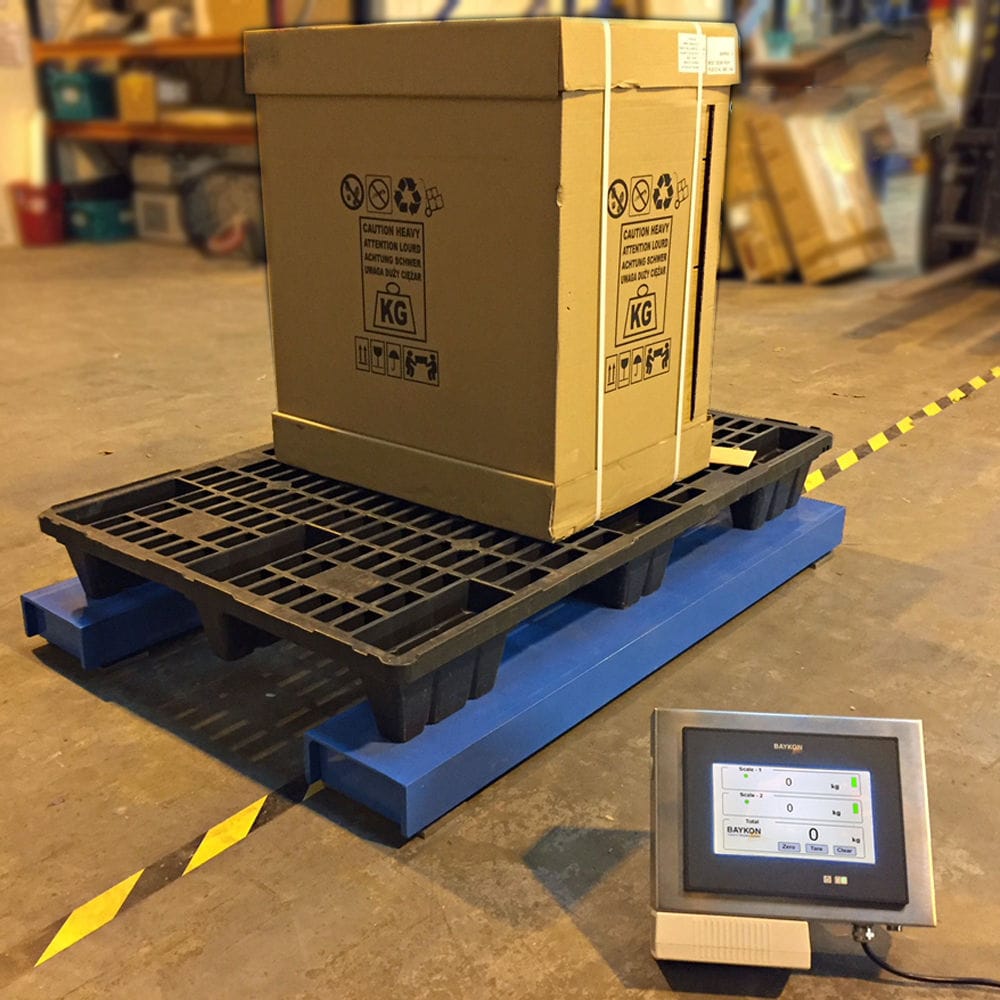


The ground balance lifting floor scale is equipped with several weighing sensors at the bottom of the platform. The electromagnetic eddy current generated on the upright column of the bucket elevator acts in opposition to the original magnetic field of the sensors, changing the impedance of the coil in the sensor. The change in impedance is converted into a pulse signal and sent to the pulse counting card of the computer for counting. After analysis by the computer program, commands are sent to the loading mechanism. The main control computer of the lifting system sends information such as production volume, lifting frequency, and lifting weighing status to the relevant area network of the mine at regular intervals.

 020-34563445
The structure design of the mid-ground scale is such that both sides are fixedly connected with fixed frames, and the inner surfaces of the two fixed frames are equipped with lifting mechanisms. The upper surface of the scale is fixedly connected with an installation block, and the inner surface of the installation block is equipped with a protective compartment. The inner surfaces of the two protective compartments are symmetrically provided with slots, and the front sides of the two protective compartments are symmetrically connected with compartment doors. The two compartment doors are connected with the protective compartments through hinges. The two lifting mechanisms of the scale each include a fixed tube, and the two fixed tubes are respectively connected with the two fixed frames through the first roller. The inner surfaces of the two fixed tubes are respectively connected with screws, and one end of each screw is fixedly connected with a base plate. The lower surfaces of the two base plates are respectively fixedly connected with support rods, and the four support rods are respectively fixedly connected with universal wheels at their ends. The outer surfaces of the two fixed tubes are respectively fixedly connected with a worm gear. The inner surfaces of the two fixed tubes are respectively provided with the first internal threads that are threadedly connected with the two screws, and the inner diameters of the two fixed tubes are adapted to the diameters of the two screws. The inner surfaces of the two fixed frames are respectively connected with rotating rods, and one end of each rotating rod is fixedly connected with a worm gear that meshes with the two worm gears, and the other end of each rotating rod is fixedly connected with a handle extending to the outside of the two fixed frames. The outer surfaces of the two fixed frames at the positions corresponding to the two rotating rods are respectively provided with the first through slots, and the inner sides of the two first through slots are respectively fixedly connected with the second rollers. The weighing installation block is in an inverted trapezoidal shape. The inner surfaces of the two installation blocks are respectively symmetrically connected with tightening bolts extending into the inner sides of the two slots. The inner surfaces of the installation blocks at the positions of the two tightening bolts are respectively provided with the first holes, and the inner sides of the two first holes are respectively provided with the second internal threads that are threadedly connected with the two tightening bolts. The lower surfaces of the four corners of the scale are respectively fixedly connected with support legs, and the lower surfaces of the four support legs are respectively fixedly connected with anti-slip pads, and the lower surfaces of the four anti-slip pads are respectively fixedly connected with anti-slip particles.
The mid-level balance platform enhances the floor scale by converting the measured weight into a 4-20mA current signal through D/A conversion. This signal is then input into one channel of the PLC analog input template, and the PLC program further converts this current signal into the corresponding weight value. The on-site data collected by the PLC is processed and transmitted to the human-machine interface (HMI) of the operation station in the main control room. According to the process requirements, various operation screens corresponding to the on-site process are set on the HMI to display the status of the on-site equipment, the actual values of various process parameters, and the system control process. By monitoring the HMI, the operator can observe the operation status of the equipment in real time. The operator can also modify the process data based on the actual situation and promptly handle alarm events. In necessary cases, manual intervention of the equipment operation can be carried out. The floor scale is equipped with several weighing sensors at the bottom of the platform. They are of photoelectric type and are designed on the derrick at the unloading point of the bucket elevator. When the bucket elevator arrives, the eddy current generated on the upright column of the bucket elevator interacts with the original magnetic field of the sensor in reverse, changing the impedance of the coil in the sensor. The change in impedance is converted into a pulse signal and sent to the pulse counting card of the computer for counting. The signal measured by the weighing sensor is amplified and shaped, and then transmitted through the signal line to the main control computer. The A/D and D/A conversion cards in the computer convert the analog quantity into digital quantity, and after analysis by the computer program, commands are sent to the loading mechanism. The main control computer of the lifting system sends information such as production volume, lifting times, and lifting weighing status to the relevant area network of the mine at regular intervals.
Raise the weighbridge and install the weighing cylinder at the bottom of the quantitative loading hopper. When using a single sensor, the quantitative loading hopper and the weighing sensor must be connected by a ball hinge, and the weighing sensor should be installed below the geometric center of the quantitative loading hopper. To eliminate the effect of loading impact loads, a damper can be set on the sensor or the signal from the sensor can be filtered first. When the load approaches 95% of the quantitative loading quantity, a signal to shut down the loading mechanism is sent. Since the loading mechanism needs a transition time to close completely, the actual loading capacity is exactly reached at this point. Additionally, due to the impact of the loaded materials on the quantitative loading hopper, the weight measured will be smaller than the actual material weight. To eliminate the influence of this factor, the time coefficient method should be used reasonably based on the dropping height and loading speed. For the crank-type loading mechanism, this influence coefficient is set at 3%. Using the signals from the quantitative loading mechanism and the lifting count, the lifting output can be statistically calculated. After the bucket is lifted to the loading point at the wellhead and unloaded automatically, the minerals are generally unloaded completely, but in some cases, a certain amount of minerals may remain in the bucket. If the bucket is directly lowered for quantitative loading, it may cause overloading during the lifting process, and in severe cases, it may even trigger an accident. Install a bucket weighing device at the wellhead of the lifting weighbridge. By subtracting the weight of the "empty bucket" weighed from the rated lifting weight, the difference obtained is the weight of the lower fixed-load loading. During the lowering of the bucket, the lower quantitative hopper prepares the amount of minerals for loading, and the weighing sensor is installed at the bottom of the pulley bearing. The weight of the bucket is calculated using the change in the support force of the bearing, and the problem of loose rope and tank locking can also be measured. During the lowering process of the bucket, if the force measured disappears or decreases, it indicates a rope loosening accident. The main control computer emits an audible and visual alarm and stops the machine (sending a control signal to the lifting weighbridge safety circuit).


