


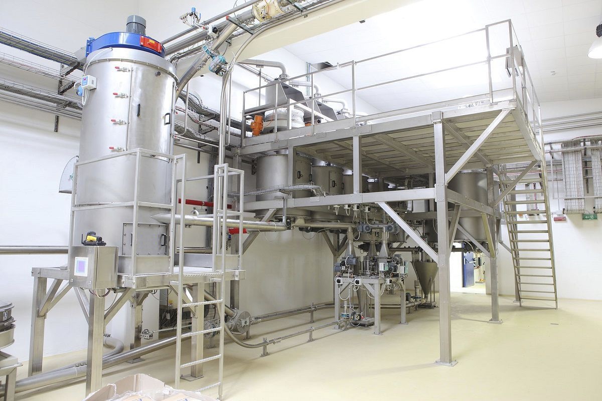


The Measurement automatic batching system realizes the weighing of powder in a vacuum environment, and the air is removed from the weighing chamber through the negative pressure pump to form a low-pressure environment, so that the static electricity, heat and wet steam on the surface of the object to be weighed are dissipated, avoiding the influence of interfering factors. By setting the air inlet, the outside air is introduced into the weighing tank to form an obvious air flow field, which ensures the uniform dispersion of the material during the weighing process, thus avoiding the problem of the weighing tank being too heavy and improving the weighing accuracy.

 020-34563445
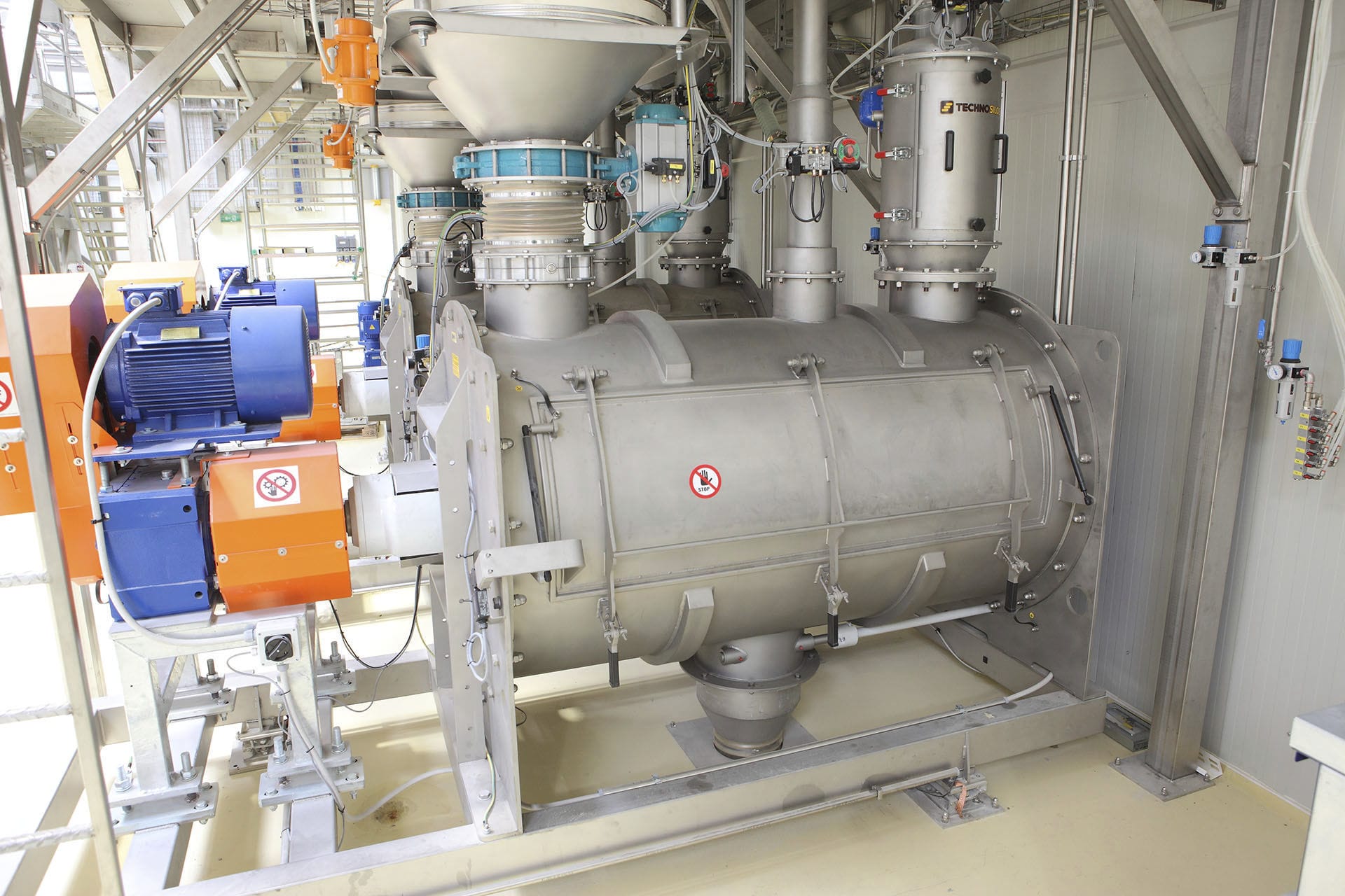
The fully automatic Batching system for metering comes in single feeding tank form, parallel type and series type. The layout requires sufficient installation space. For the feeding of carbon black, in order to reduce the crushing rate of carbon black, large-volume feeding tanks should be adopted, and they are generally arranged in parallel. It is best to design the volume of the pressure feeding tank to be equal to that of the corresponding space bag for carbon black packaging, in order to improve the feeding efficiency. The design pressure of the pressure delivery tank is generally no less than 0.45MPa, and it is best to design it as 0.60MPa. The pressure delivery tank is a pressure vessel and must be designed, processed and inspected in accordance with relevant national standards. A safety valve needs to be installed on the top of the pressure delivery tank. The exhaust capacity of the safety valve shall be calculated in accordance with the relief area of the relief device in Clause B.8 of Appendix B of the national standard GB150.1--2011 "Pressure Vessels - Part 1: General Requirements". The size of the safety valve is related to the volume of the pressure delivery tank, the air flow rate for feeding and cleaning (referred to as the air volume), and the size of the intake pipe. The specifications of safety valves for feeding systems with different feeding pipe diameters should be different.
Pneumatic feeding relies on compressed air. The size of the compressed air flow rate affects key indicators such as the feeding capacity, feeding state, and feeding energy consumption of pneumatic feeding. A reasonable feeding air volume can reduce the air velocity (referred to as air velocity) in the feeding pipeline, alleviate pipeline wear, lower the breakage rate of feeding material particles, and decrease pressure loss and energy consumption, etc. When designing the pneumatic feeding system for carbon black, the control of air volume is particularly important, especially for reducing the crushing rate of carbon black particles. At present, the feeding of carbon black usually adopts dense-phase feeding, which can achieve a relatively large material-to-gas ratio. However, for the same system, the maximum material-to-gas ratio that can be achieved for one material under certain feeding conditions is limited. If the material-to-gas ratio is too large, pipe blockage may occur. When designing, the supply volume of compressed air should be determined based on the capacity of the Feeder and the pressure changes in the feeding pipeline. Only in this way can the highest feed-to-air ratio be achieved without pipe blockage.
The geometric distance for feeding carbon black pneumatic conveyors is generally 30 to 200 meters. One feeding system can feed multiple types of carbon black and can provide the amount of carbon black for multiple sets of auxiliary machine systems to meet different feeding distances. It is very important to adopt different feeding air flow rates according to different materials and different feeding distances. At present, there are several ways to control air flow:
1) The combination mode of manual pressure reducing valve and fixed Laval pipe. The air flow cannot be automatically adjusted. Once the debugging is completed, the air flow remains unchanged. For short distances, a set of auxiliary machine system (with little change in the feeding distance) is relatively economical.
2) The combination method of proportional valve and fixed Laval pipe. The air flow is controllable within a certain range. The inlet pressure of the Laval pipe is adjusted by automatically changing the set pressure of the proportional valve, thereby regulating the flow. According to the pressure requirements of the feeding resistance and the critical flow of the Laval tube, the set pressure of the proportional valve generally should not be less than 0.25MPa, usually ranging from 0.25 to 0.35MPa. Excessive pressure will affect the service life of the aluminum alloy lined rubber tube. The resistance of the feeding pipeline is preferably less than 0.20MPa, generally ranging from 0.10 to 0.15MPa. Especially for systems where the feeding distances of different target tanks differ by more than 100 meters, it is very difficult to control the gas velocities of different carbon blacks and different target tanks within a reasonable range.
3) Pressure reducing valve and automatic adjustable Laval pipe gas volume automatic control system. This feeding method is a commonly adopted air volume control method by internationally renowned pneumatic feeding equipment companies at present. Most of them are patented products, with a wide air volume control range, especially suitable for different materials and different feeding distances, and stable and accurate air volume control.
4) The combination mode of pressure reducing valve and flow regulating valve. At present, a feeding method has been introduced, which is automatically controlled by one pressure reducing valve and two flow regulating valves to regulate the air flow of the pressure delivery tank and the auxiliary pipe. The air flow of the auxiliary pipe accounts for approximately 50% of the total feeding air volume. The feeding distance is less than 100m, and the air flow velocity at the end of the feeding pipe is less than 7.5m/s. The pressure of the main and auxiliary feeding pipes is controlled by a pressure reducing valve. A large-sized pressure reducing valve is required, for example, if the diameter of the feeding pipe is 225mm, the inner diameter of the main air source pipe is 100mm, and the diameter of the pressure reducing valve is 100mm. No matter which control method is adopted, pressure reducing valves, proportional valves and air filters are generally indispensable. The selection has a very important impact on the performance of the pneumatic feeding system.


