


Hopper scales are used for weighing product streams for packaging, dosing, dispensing and yield monitoring in batches. The unit consists of a hopper, weighing cell and weighing instrument. It is an ideal automatic weighing device for the modernization of bulk materials, mainly divided into totalizing hopper scales and loss-in-weight feeding scales.


 020-34563445
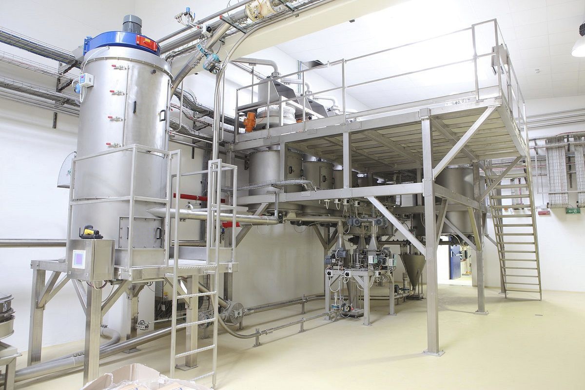
The weightless hopper scale mainly consists of the upper hopper part on the scale, the hopper weighing part, the lower hopper part on the scale, the automatic screw device, the scale body support, the weighing control system, and the industrial control computer management system. The upper hopper part is composed of the storage hopper, the feeding gate, and the level sensor, etc. The storage hopper is used to temporarily store the materials when the hopper weighing part is conducting accumulation and screwing. The hopper weighing part is composed of the hopper weighing body, the screw gate, the weighing module, etc. This part together with the weighing control part forms the basic measurement unit of the bulk material scale. The lower hopper is composed of the discharge hopper and the level sensor. The discharge hopper receives the materials from the hopper weighing part and gradually discharges the materials. The batching control system is mainly composed of the weighing module, the weighing control cabinet, the level sensor, etc., controlling the operation of the non-continuous cumulative automatic hopper scale and serving as the central hub of the entire bulk material scale measurement. The industrial control computer management system is installed in the control room, responsible for collecting the weight data of the control system, comprehensively monitoring the system's operation, and being able to program and modify the weighing control parameters through the window software for the PLC.
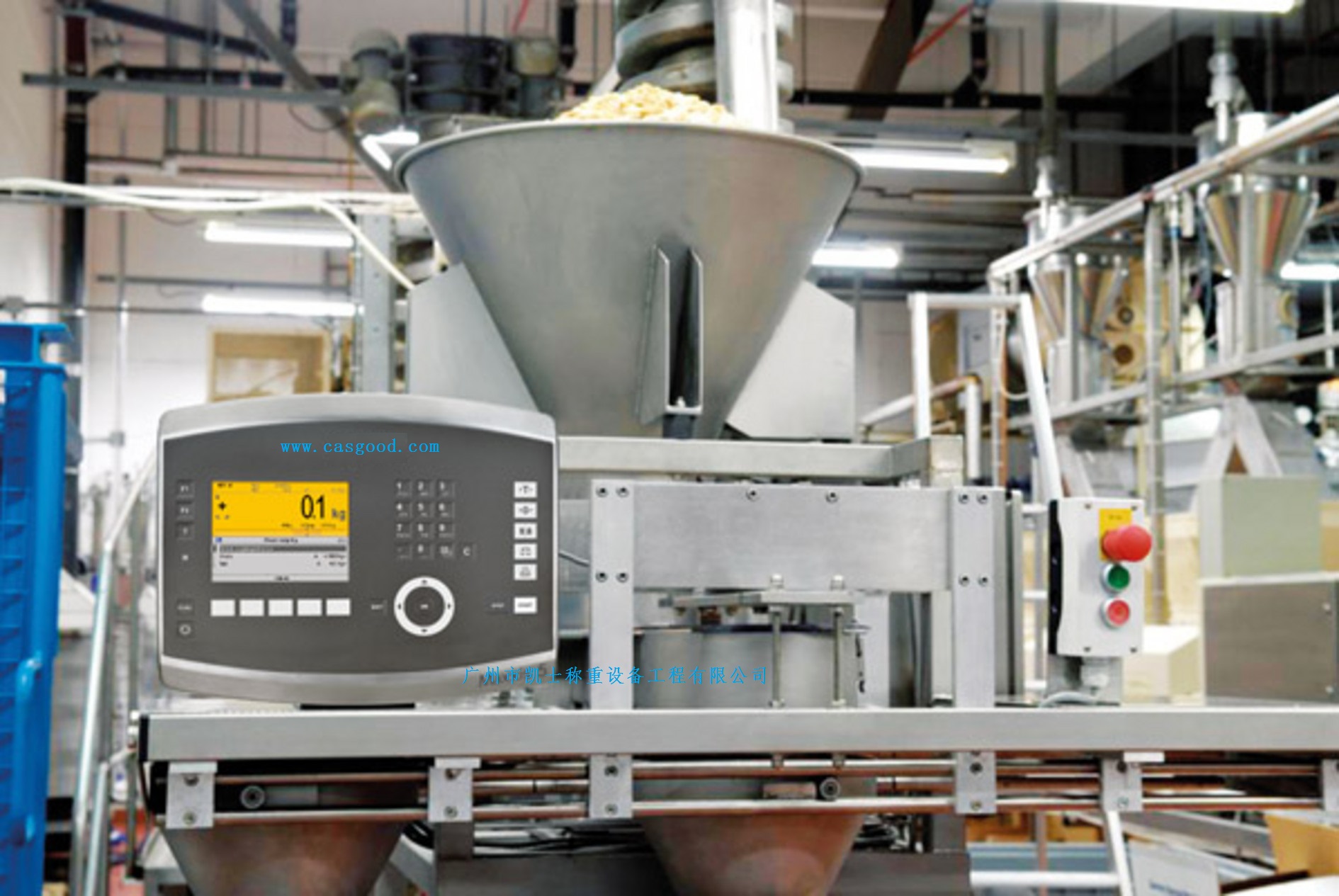
When the hopper is empty, close the door at the hopper end on the scale, automatically reset the weight of the hopper scale, and the material conveyed by the screw conveyor enters the hopper at the scale end. The feeding process: close the gate at the hopper scale end, open the door at the scale end, and the material enters the hopper at the scale end and proceeds to the feeding section; when the required weight per scale is reached, close the door at the scale end of the hopper to start weighing and metering, automatically store and accumulate the weight value of this scale, and complete the metering of the screw process. After the screw process is completed, the door at the scale end of the hopper opens, and the material is discharged into the lower hopper of the scale. When the screw conveying of the hopper scale is completed, close the gate at the hopper scale end, reset the weight of the hopper scale automatically, and enter the next weighing cycle. During the entire weighing process, there is no gate at the lower hopper of the scale, and the feeding from the scale end hopper to the screw conveyor is always continuous and stable, and the feeding screw conveyor at the scale end hopper also always operates continuously and stably. According to the closing and opening of the gates at the scale end and the hopper scale, as well as the stable time required by the weighing of the scale end hopper and the hopper scale, achieve static weighing while meeting the requirements of continuous conveying.
When the hopper scale is weighing the materials, it changes and sets the quantitative range of the weighing instrument based on the weight of the materials input measured by the weighing module. It retrieves the required measurement range setting points from the weighing instrument and controls the frequency converter to perform coarse feeding operation into the hopper scale according to the preset feeding program. When the weight in the hopper of the hopper scale changes, the weighing module inputs the detected signal into the weighing controller. After a series of processing, it re-changes and sets the quantitative range of the hopper scale instrument based on the processing results. It determines whether the coarse feeding set value is reached. If it is reached, it controls the frequency converter to perform fine feeding, that is, to slowly feed materials into the hopper at a slow speed. Conversely, if it has not reached the set coarse feeding value, it will again perform coarse feeding into the hopper until the set coarse feeding value is reached. When performing fine feeding into the hopper, the weighing sensor of the hopper scale detects the change in the fine feeding set value. If it reaches the set fine feeding set value, it controls the frequency converter to stop performing fine feeding into the hopper. At this time, it is necessary to determine whether the weight display on the instrument panel is stable and there is no deviation. If it has not reached the set fine feeding set value, it will continue to perform fine feeding into the hopper until the set value is reached. After reaching the set fine feeding set value, the weight in the entire hopper meets the weight requirement for a single feeding. At this point, the hopper valve is opened to perform the discharge operation. After the discharge is completed, the instrument panel of the hopper scale is reset to zero, the hopper discharge valve is closed, and a single material feeding measurement operation is completed. Thus, the automatic measurement of the hopper scale is completed.
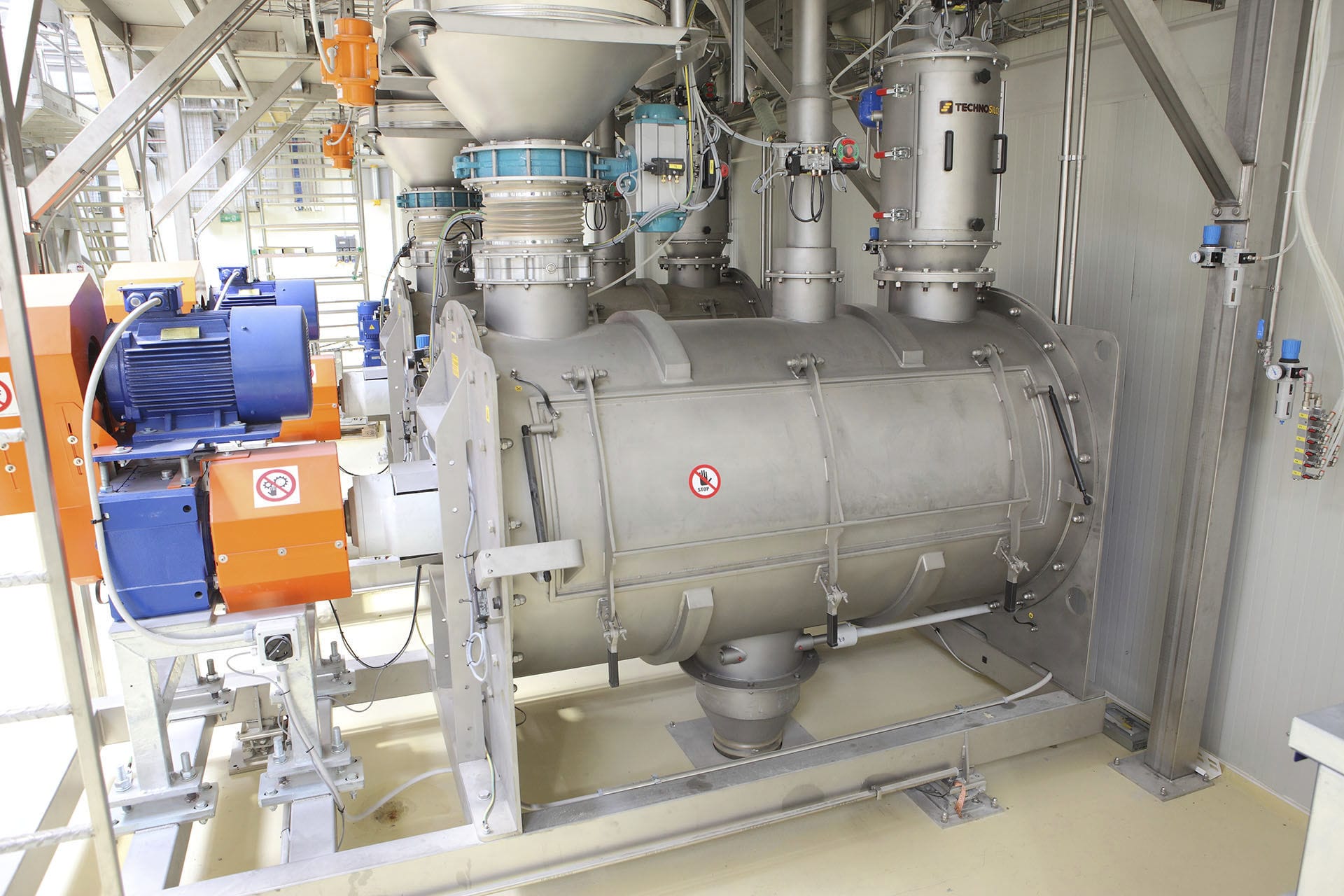
The weighing Feeder includes a metering cutter, a variable-speed rotary feeding valve, a weighing instrument, a frequency converter, a weighing module and the corresponding control electrical components, etc. It realizes point-to-point communication between the industrial control computer and the PLC. The industrial control computer sends the target output to the weighing instrument, and the weighing instrument outputs control signals to adjust the output frequency of the frequency converter, changing the rotational speed of the variable-speed feeding cutter motor. The weighing module detects the weight of the material in the metering cutter and transmits the signal to the weighing instrument. The weighing instrument calculates the current instantaneous flow of the material based on the sensor signal and uploads it to the industrial control computer. The weighing instrument performs PID calculation based on the target output, adjusts the control signal of the frequency converter, changes the motor speed, and makes the instantaneous flow reach the target output.
The Weighing system transmits the screw load and speed signals to the microprocessor-controlled measurement, control and regulation system for processing. It continuously compares the feeding rate with the set rate, thereby controlling the screw speed and maintaining the feeding rate at a constant level. Usually, the integral method or cumulative method can be used to calculate the instantaneous flow value and the cumulative flow value. The instantaneous flow refers to the weight of the material flowing through the screw scale within a unit time (or at a certain moment); the cumulative flow value refers to the total amount of material flowing through the screw scale within a certain period of time.


