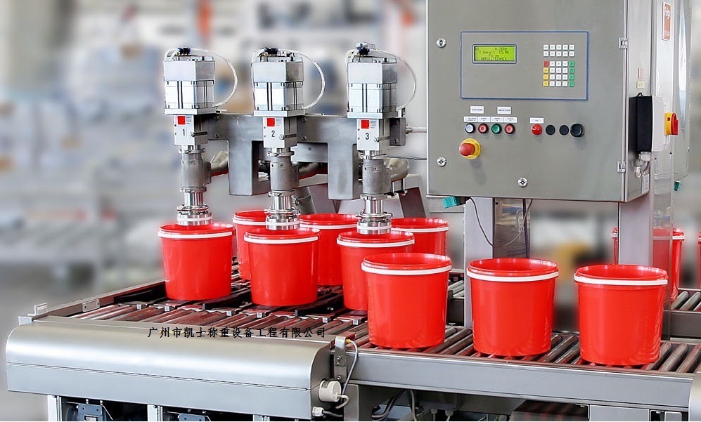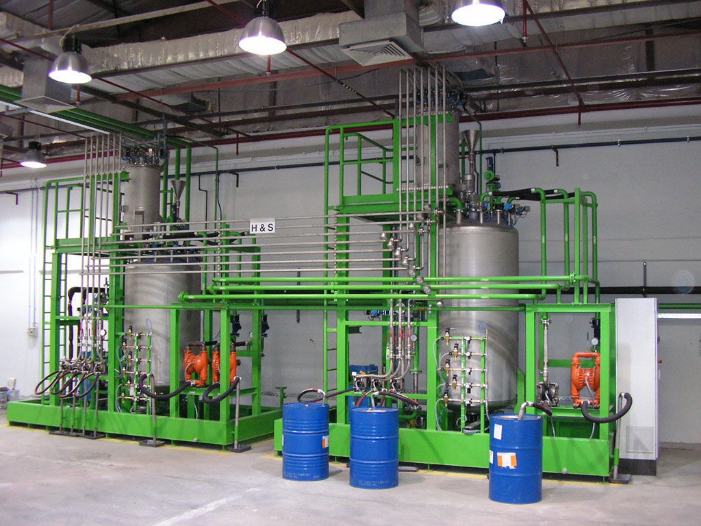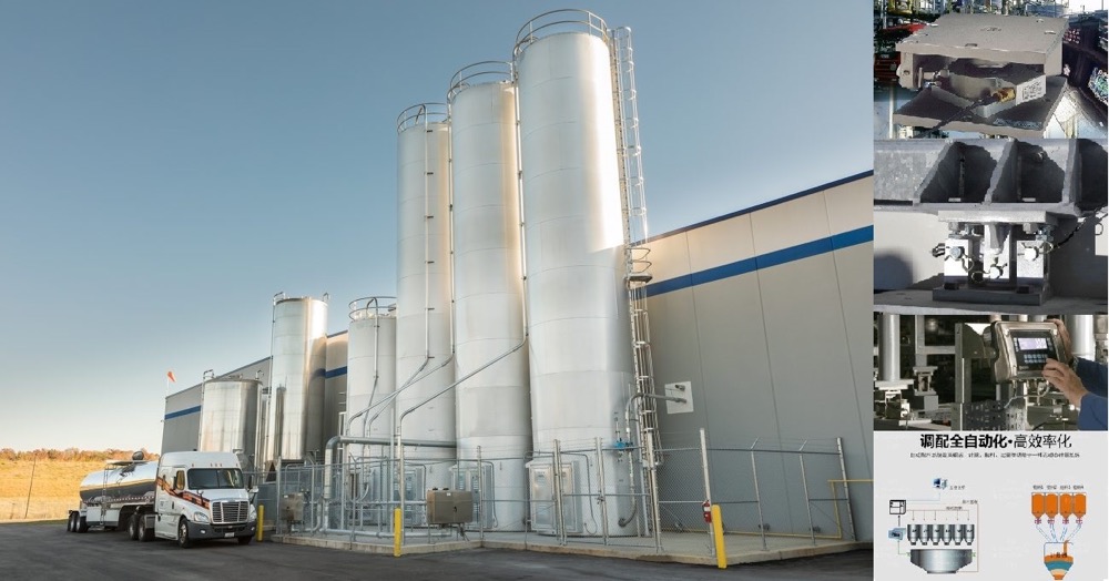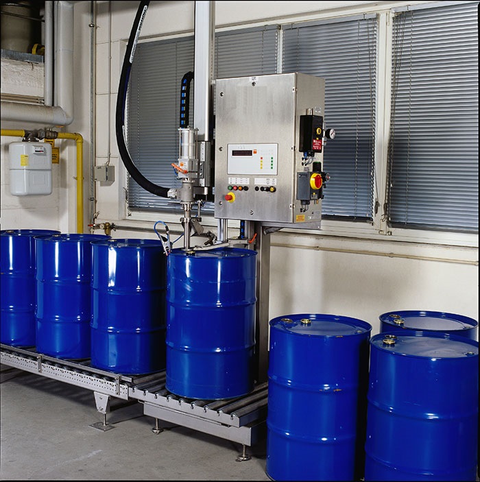


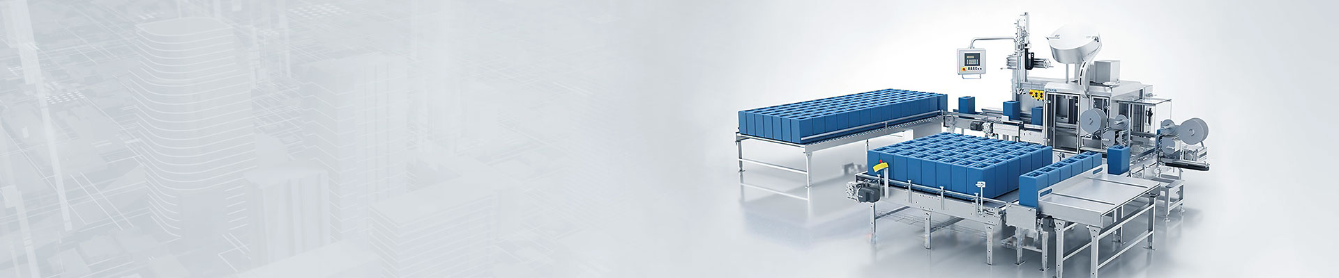


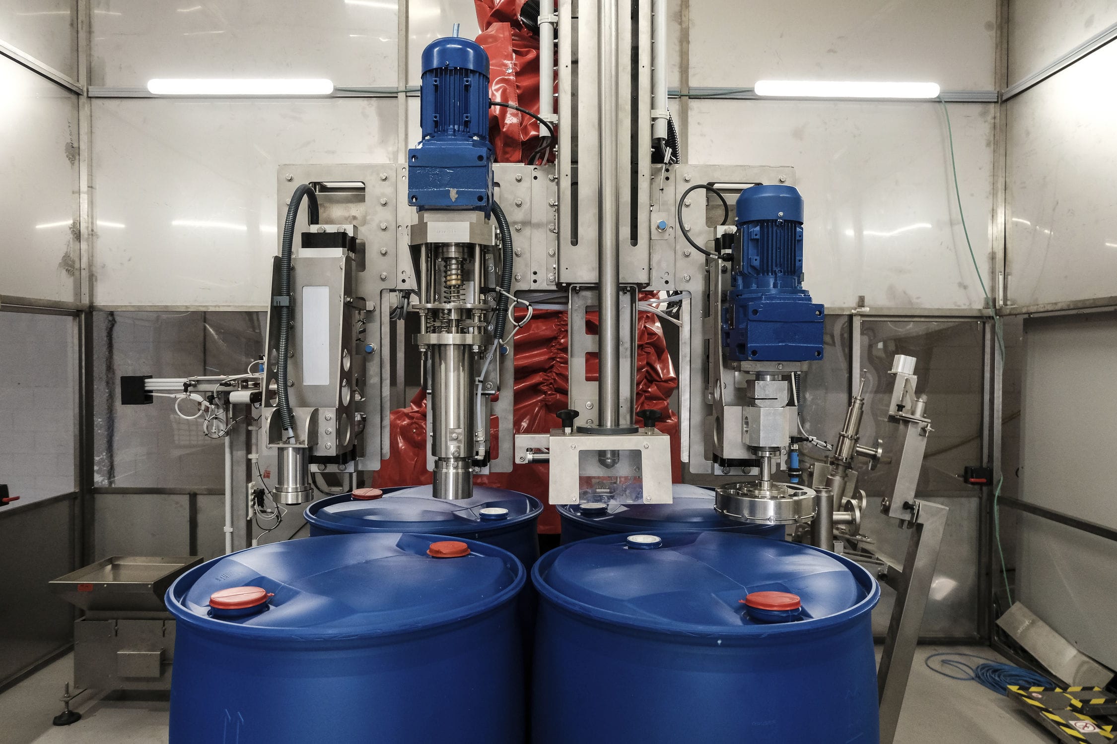
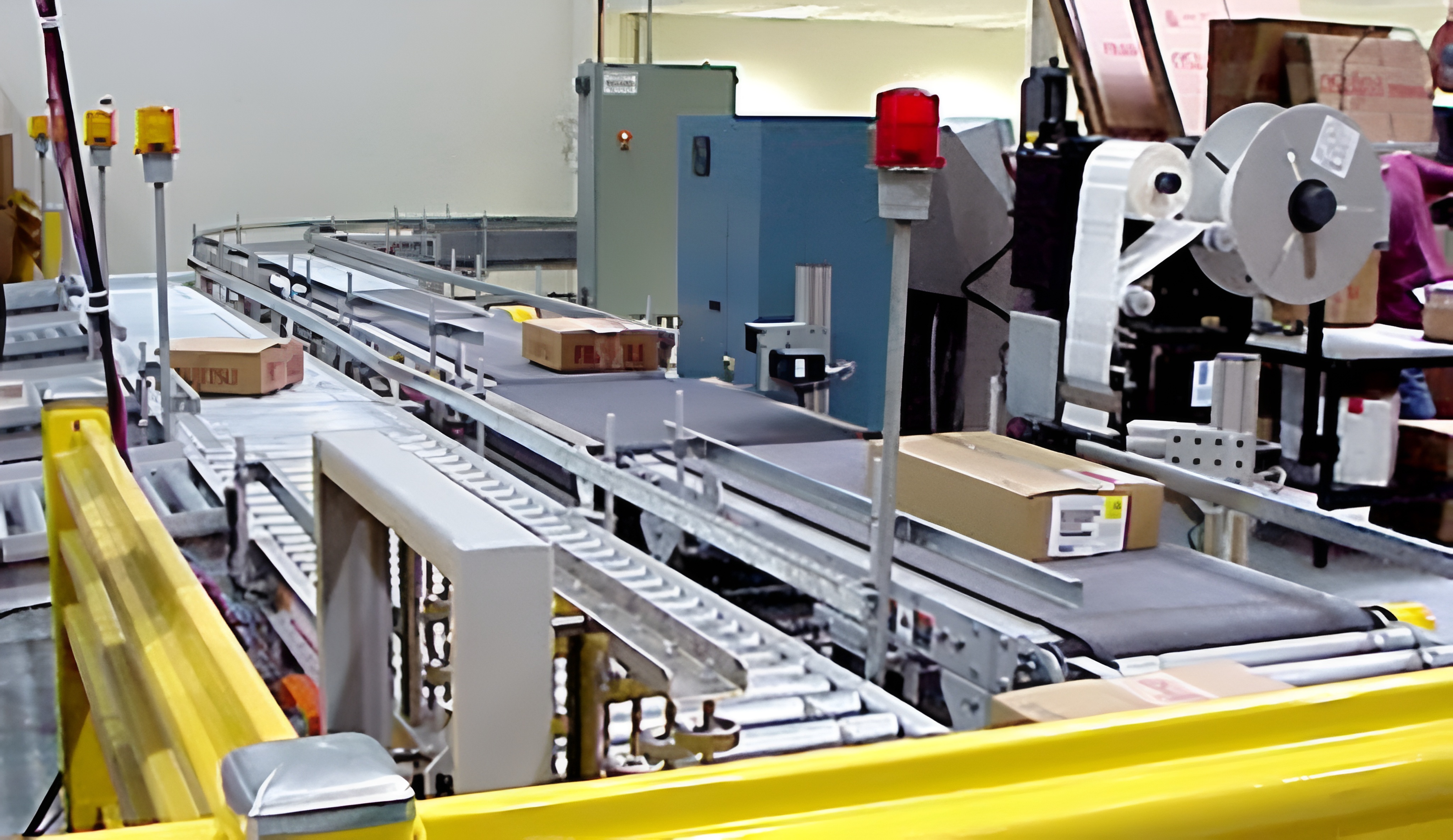
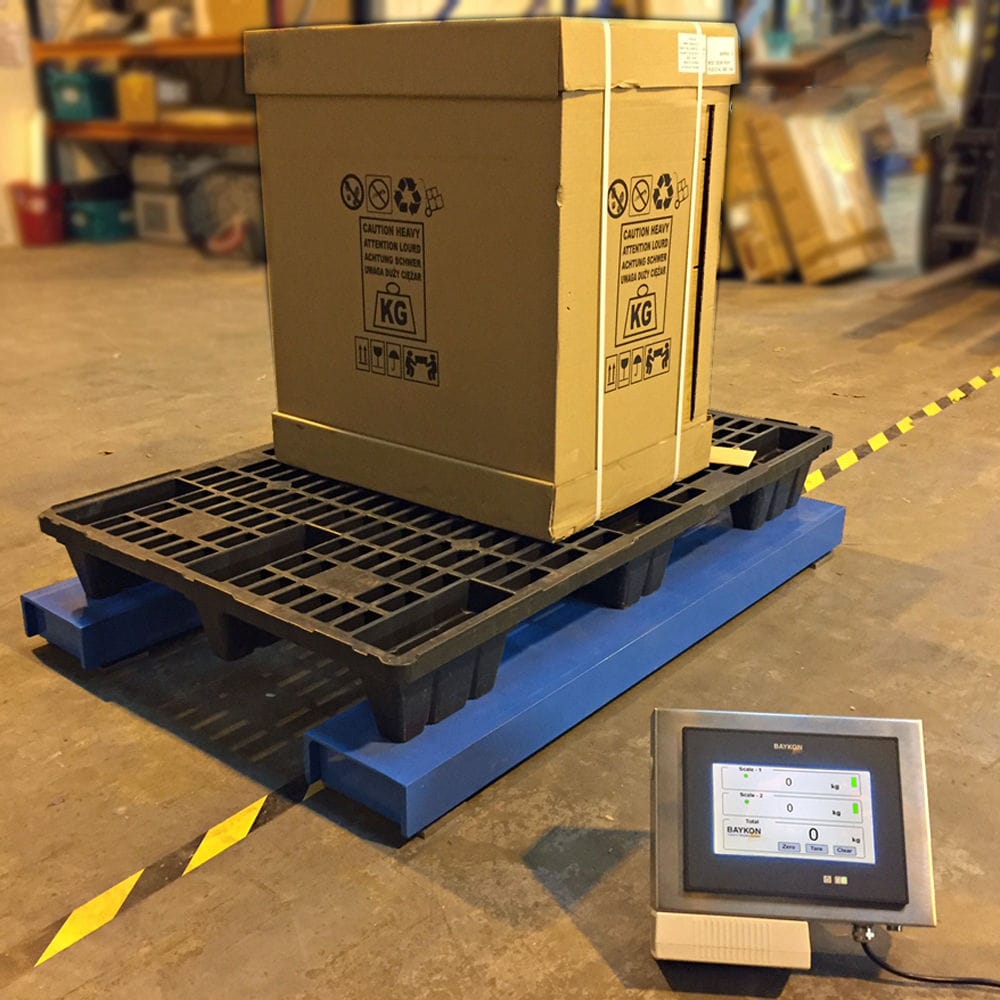


Coolant Automatic filling machine adopts new carbon dioxide blowing process, reduce carbon dioxide consumption, reduce oxygen pickup, filling display material amount, operation status, various alarm instructions, each filling amount, according to the process requirements of uniform settings, can be collected and processed by each filling control circuit to weighing signals and switching status, to realize the entire filling system feeding, weighing and detection, material adjustment, selection and switching of containers, such as dosing Automatic control of the process.

 020-34563445
The automatic frozen liquid Filling machine adopts the highly reliable Siemens PLC S7-300 control system as the main automation facility for on-site data acquisition circuit control, sequential control operation, and calculation, realizing the operation diagnosis, real-time monitoring, automatic control, etc. of the Filling system, meeting the requirements of real-time, stability, and reliability of the system. The touch screen configuration adopts an intelligent multifunctional panel, and the human-machine operation interface is simple, suitable for configuration, and easy to modify, achieving a complete human-machine dialogue state. The filling system and PLC control system can communicate and set up quickly through the RS-422/485 interface. The input analog signals of external parties in the entire control system (AD has alarm signals for various probes such as pressure, weight, liquid level, humidity, etc.); There are also all button switch signals and cylinder switch signal (DIDO) signals. The main control indicators for filling weight are to determine whether the relevant indicators of initial and re weighing meet the weighing requirements. The automatic adjustment of the liquid level in the storage tank and intermediate tank during the filling process, as well as the control design of the external handheld barcode scanner, are also important links in the control part. The configuration and external wiring of the filling machine include one expandable analog input/output module, which has a programmable controller with networking communication function for switch input and switch output. The PLC's built-in basic control unit can be used to design its start and stop.
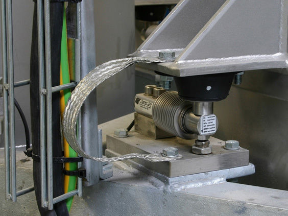
The Liquid filling machine is equipped with a conveyor belt on the top of the support platform, and a limit mechanism is installed on one side of the top of the conveyor belt. An extension plate is installed on the other side of the support platform, and a support seat is installed on the top of the extension plate. A filling box is installed on the top of the support seat, and a filling head is installed on one side of the bottom of the filling box. An anti splash disk is installed on the outside of the filling head to prevent splashing. An electronic weighing scale is installed on the bottom of the conveyor belt to calculate the load-bearing capacity. The start and stop of the filling head are controlled by a control box, thereby achieving the purpose of automatic and quantitative filling. The limit mechanism of the quantitative filling machine includes three parallel fixed rods, with an outer plate set on the outside of the three fixed rods. Two limit rods are installed on the side wall of the outer plate through a rotating shaft seat. There are several telescopic rods installed between the side of the limit rod and the outer plate, and several guide wheels are installed on the outside of the limit rod. The two limit rods can be adjusted to tilt by the telescopic rods, and can play a guiding role when the guide wheels contact the outer wall of the canning device.
The automatic filling machine is connected to the limit rod and the outer wall of the outer plate at both ends of the telescopic rod through a rotating shaft. The rotating shaft is set to connect the telescopic rod, allowing for flexible adjustment of its tilt angle. Two limit rods are arranged horizontally in a straight line, and the ends of the two limit rods do not touch. The two limit rods are arranged in a straight line and in opposite directions, forming a V-shaped structure that facilitates limiting the path of the filling equipment. The bottom of the anti splash disk is connected with a bellows sleeve, and the inner bottom of the bellows sleeve is connected with a sealing ring. The bottom of the anti splash disk is installed with an adsorption cotton plate on the inner side of the bellows sleeve, which adsorbs the filling liquid. A rubber snap ring is set at the center of the inner side of the anti splash disk, which is clamped to the outside of the filling head through the rubber snap ring. The rubber snap ring is set to facilitate the clamping and fixing of the anti splash disk. When using the weighing filling machine, the filling equipment is first placed on the top of the conveyor belt, and the travel route of the filling equipment is limited by a limit mechanism. The fixed rod is installed on one side of the top of the conveyor belt, and an outer plate is wrapped around it. By pulling the limit rod, it tilts under the rotation of the shaft seat. At the same time, different telescopic rods are extended to different lengths, and the limit rod is tilted. The filling equipment contacts the surface of the guide wheel as the conveyor belt travels, and is guided directly below the filling head to achieve precise filling effect. This improves the applicability of the conveyor belt to filling equipment of different specifications and sizes under the action of the limit mechanism, and has a wider range of use. During filling, the anti splash disk is clamped by a rubber snap ring. Outside the filling head, the filling head at the bottom of the filling box extends into the filling equipment, Perform filling exploration by pulling the sealing ring to unfold the corrugated tube sleeve, thereby wrapping the outside of the filling head to avoid splashing during filling. The liquid splashed during filling is trapped inside the corrugated tube sleeve, and the adsorption cotton board can also absorb it, greatly reducing the occurrence of splashing.
Basic Parameters:
Maximum weighing capacity: 1000kg
Minimum sensitivity: 0.2kg
Filling error: ± 0.2-0.5kg
Filling speed: 1000L, approximately 50-80 barrels per hour
Control mode: 2nd gear control
Filling method: Insertion type, above liquid level
Gun head pipeline: PTFE gun head, valve+PTFE hose
Structural material: SUS304 stainless steel for the host, carbon steel for conveying and stacking with anti-corrosion paint.
Scale platform size: 1200 × 1200mm (304 stainless steel power raceway)
Empty bucket raceway: 1200mm × 2500mm (304 stainless steel power raceway) with an additional 1200mm sloping unpowered drum
Heavy bucket raceway: 1200mm × 2500mm (304 stainless steel power raceway, 2 sets)
Bucket sorting device: suitable for 1000L buckets, carbon steel anti-corrosion paint structure, 304 stainless steel raceway.
Stacking equipment: translation type, suitable for pallets of 1200 × 1200 × 140mm, including pallet supply, palletizing, and lower pallet conveying.
Pipeline pressure: 0.2-0.6MPa (depending on material properties).
Material interface: 4 DN40 flange joints, available according to user provided interface standards
Air source interface: The user provides a 12mm air hose connector for quick connector connection
Power supply: AC220/50Hz (provided by the user to the machine side)
Gas source used: 0.4-0.8Mpa (provided by the user to one side of the machine)
Operating temperature: -10 ℃ -50 ℃
Basic conditions: A solid concrete floor with a flat coating, and the concrete thickness should be greater than 10cm.
Optional models: Standard, Explosion proof Filling