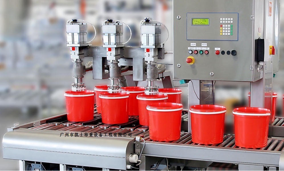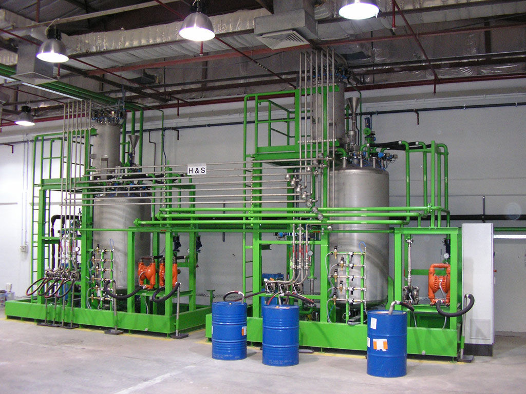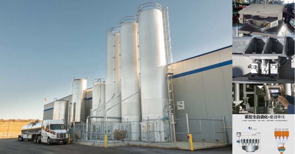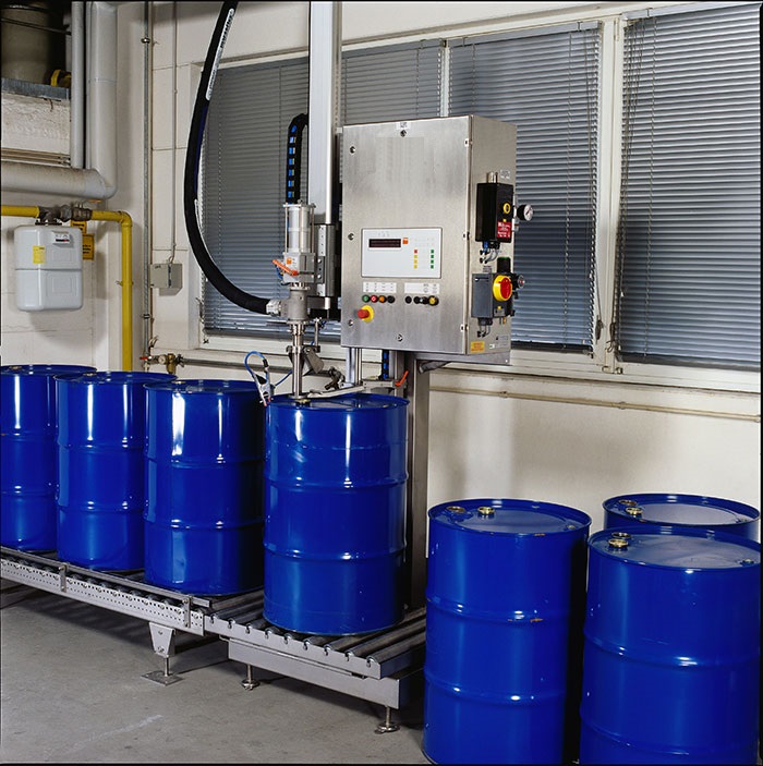


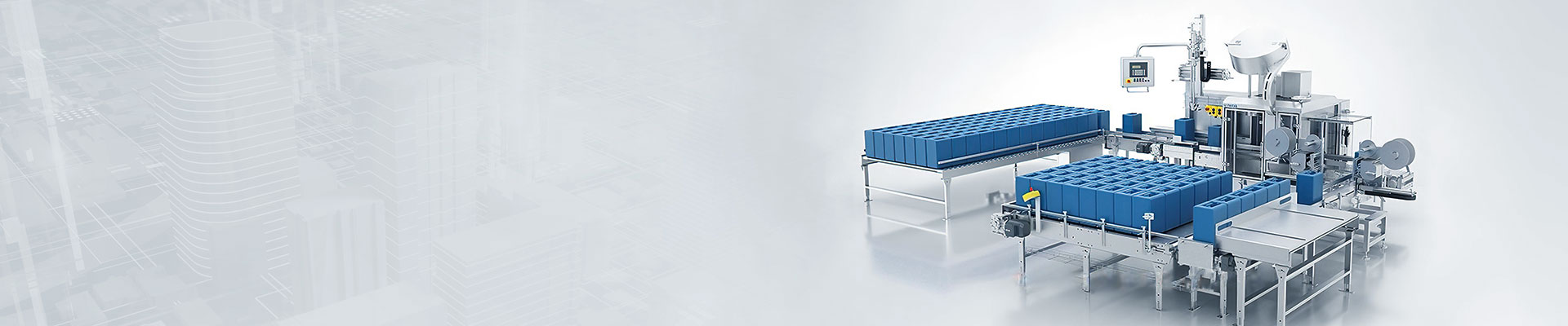






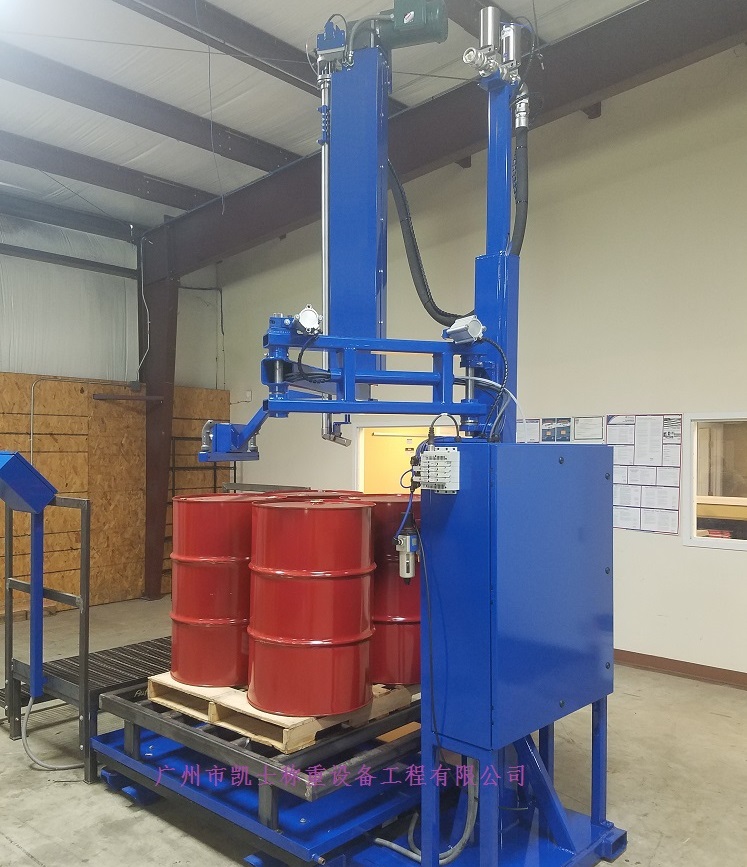
The explosion-proof filling scale mainly consists of a steel structure support platform, a scale body base, an electronic scale body, a horizontal moving frame, left and right guide rail lifting brackets, lifting linear slide rails, left and right lifting cylinders, front positioning mechanism, right positioning mechanism, stepper motor, transmission gear rack and pinion, material hose, filling head lifting cylinder, filling ball valve, pneumatic control box, positive pressure control cabinet, etc.

 020-34563445
The explosion-proof filling scale adopts a configuration software for the monitoring interface, which can quickly construct and generate an upper computer monitoring system. Through data collection and processing at the site, it displays animations, handles alarms, and implements process control. Real-time curves, historical curves, and report outputs are provided. To meet the above monitoring requirements, in the monitoring interface, a filling effect and a fast-flowing attribute setting simulate the dynamic filling process. By adding standard buttons, manual/automatic selection, start, stop, emergency stop, and manual opening of the pump electromagnetic valve can be achieved. Through setting the display output attributes of the labels, the setting of filling quality, the setting of the number of filled barrels, and the display of the current number of filled barrels can be realized. These configuration monitoring screens are completed to monitor the operating status of the Filling system.
The filling scale uses an AC servo system, with speed and current loop PI proportional control. A PID loop is introduced in each repetitive controller channel to adjust the system's tracking performance. The integrated PID control and the improved dual repetitive control system achieve rapid convergence of repetitive errors and effective suppression of interference signals. The input signal is provided by a photoelectric encoder installed coaxially with the rotating disc of the bucket to be filled, and the signal is processed through multiple levels of filtering. To improve production efficiency and filling quality, the improved dual repetitive controller and conventional PID control are applied to the horizontal tracking and rapid swing servo system of the Filling machine, taking advantage of their respective strengths to achieve high-precision tracking of periodic signals and effectively reducing repetitive errors.
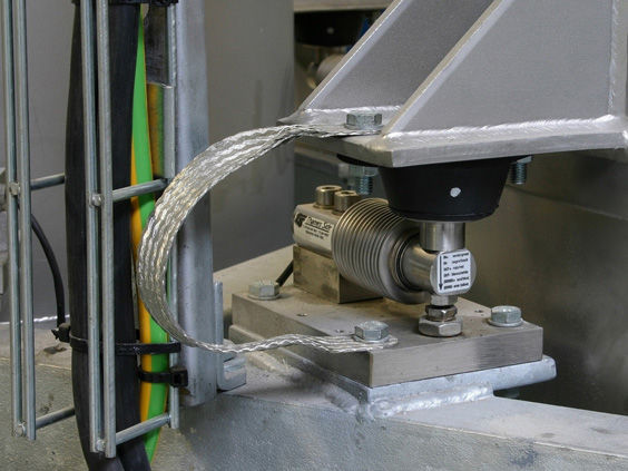
The quantitative scale is equipped with stepper motors, electronic weighing platform, pneumatic solenoid valves, proximity switches, switch button boxes, etc. The weighing sensors of the scale are connected to the weighing instrument through sensor junction boxes and intrinsically safe safety barriers. The PLC communicates with the weighing instrument through serial communication. The intrinsically safe proximity switches transmit signals to the PLC through explosion-proof junction boxes and transformer-isolated safety barriers. The PLC controls the stepper driver, which in turn drives the stepper motor to operate. The stepper motor drives the transmission gear rack. The indicator lights serve as indicators for filling status and alarm status output, etc. The relays are used for indirect control of the diaphragm pump start and stop. The touch screen communicates with the PLC for filling machine debugging, parameter setting, data display, status and alarm output, etc.
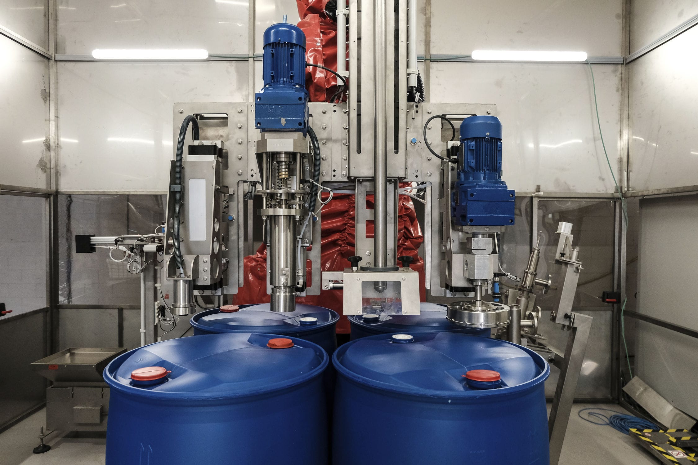
The filling system mainly consists of a steel structure support platform, a scale body base, an Electronic scale body, a horizontal moving frame, left and right guide rail lifting brackets, lifting linear slide rails, left and right lifting cylinders, front positioning mechanism, right positioning mechanism, stepper motor, transmission gear rack and pinion, material hose, filling head lifting cylinder, filling ball valve, pneumatic control box, positive pressure control cabinet, etc. The maximum range of the scale body is 1500kg with a graduation value of 0.5kg. The steel structure support platform plays a supporting and framework role for all components of the filling machine. The front and right positioning mechanisms are used to position when placing the empty filling barrels, ensuring the fixity of the square barrels. The left and right lifting cylinders can move the entire four-gun head spray gun assembly up or down, thereby achieving the filling of double-layer barrels. The lifting cylinders are equipped with linear slide rails on both sides. The design of the four spray guns realizes that one-time lifting of the spray gun can continuously fill four barrels of materials, effectively improving the filling efficiency. The four-bar spray gun and its components are fixed on the horizontal moving frame. The stepper motor realizes the precise positioning function of the front and rear movement of the spray gun assembly through the transmission gear rack and pinion on the left side of the driving device. The two extreme positions of the front and rear movement of the four spray gun components are respectively equipped with extreme position detection switches and zero-point detection switches. There is one pneumatic control box on the right side and one on the rear side, used to install the pneumatic control elements of the quantitative filling machine. The filling head lifting cylinder is used to lower the spray gun into the barrel before filling and raise the spray gun out of the barrel after filling. The liquid material is transported through the material pipeline and then sent to the filling valve of each bar spray gun through the material hose. The 200L and IBC barrels filling ball valves are used as backup configurations for this filling machine. The positive pressure control cabinet is equipped with PLC, touch screen, weighing instrument and other electrical components, used for explosion-proof scenarios, and placed next to the filling machine.
When the electronic scale operates in the automatic filling mode, after manually placing one layer of empty buckets or two layers of empty buckets, the positioning switches for one layer or two layers can be operated to control the movement and positioning of the front positioning cylinder and the right positioning cylinder. Then, the empty buckets can be shaped manually to achieve the fixed position placement of one layer of empty buckets or two layers of empty buckets. After one layer of empty buckets is ready, press the "One Layer Start" button. The left and right lifting cylinders will automatically descend to the set position, and then the step system drives the spray gun device to move from the zero point forward to the position directly above the top of the first row of buckets and stop. The filling head's spray gun will automatically descend and the four-bar spray gun will be inserted into the four bucket mouths respectively. Then, the first bucket of the first row will be filled at a fixed value. After the first bucket is filled, the second bucket will be filled. This process continues until all four buckets in the first row are filled in sequence. After the filling of all four empty buckets in the first row is completed and the spray gun head is detected to be raised to the correct position, the step system drives the spray gun device to return to the zero point position. Then, the left and right lifting cylinders operate to lift the spray gun device up and detect its position. The same control requirements are followed to complete the filling of the empty buckets in the third row. After all four empty buckets in the first row are filled and the spray gun head is detected to be raised to the correct position, the step system drives the spray gun device back to the zero point position, and then the left and right lifting cylinders operate to lift the spray gun device up and detect its position.
During the filling process of the explosion-proof scale, it is carried out in two batches. First, the first layer of square barrels (placed closely against the tray is considered as the first layer) is set up. Then, the first batch of filling is completed, which means filling all 12 barrels in the first layer. Next, the second layer of square barrels is placed, and the second batch of filling is carried out. Each layer of square barrels consists of 12 barrels, arranged in 3 rows and 4 columns. The rows are defined from the back to the front: the 1st row, the 2nd row, and the 3rd row. The automatic filling machine's material start and stop are achieved through indirect control of the diaphragm pump by PLC. Fast feeding and slow feeding are realized by controlling the fast and slow feeding coils of the corresponding filling valves for each rod spray gun during the stage of manually placing empty barrels before filling. The actions of the front-side and right-side positioning cylinders are controlled by PLC to ensure the fixity of the rear side and right side positions of the empty barrels. When manually placing the empty barrels, just place the empty barrels closely against the rear side and right-side positioning plates, and place all the empty barrels closely together, with the barrel mouths facing in the same direction. The left and right lifting cylinders can lift or lower the entire spray gun assembly. When the assembly is in the lowered position, it can fill the first layer of square barrels. When the assembly is in the lifted position, it can fill the second layer of square barrels. The PLC controls the step system to achieve precise positioning of the barrel mouths in the front-back direction of each row; through debugging, the spacing of the four-bar spray gun is made consistent with the lateral spacing of the barrel mouths, thus achieving precise positioning in the left and right directions. After the automatic finding of the barrel mouths is completed, the PLC controls the filling valves of the spray gun to perform fixed-value filling one barrel at a time based on the received weighing data.