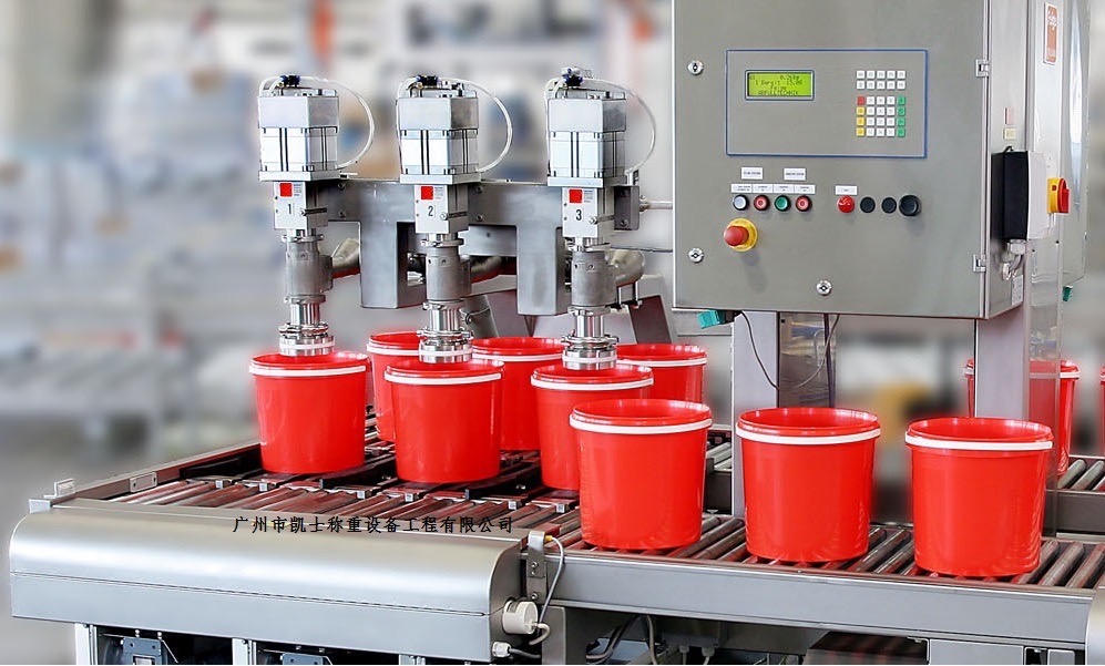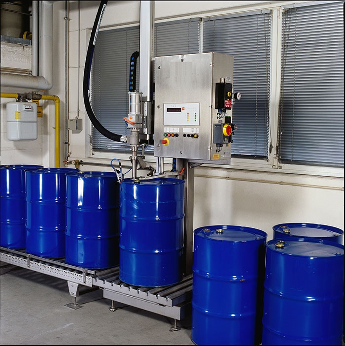


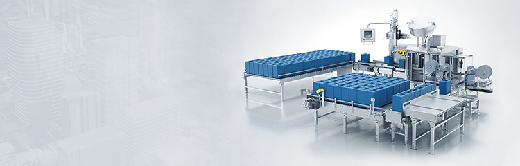


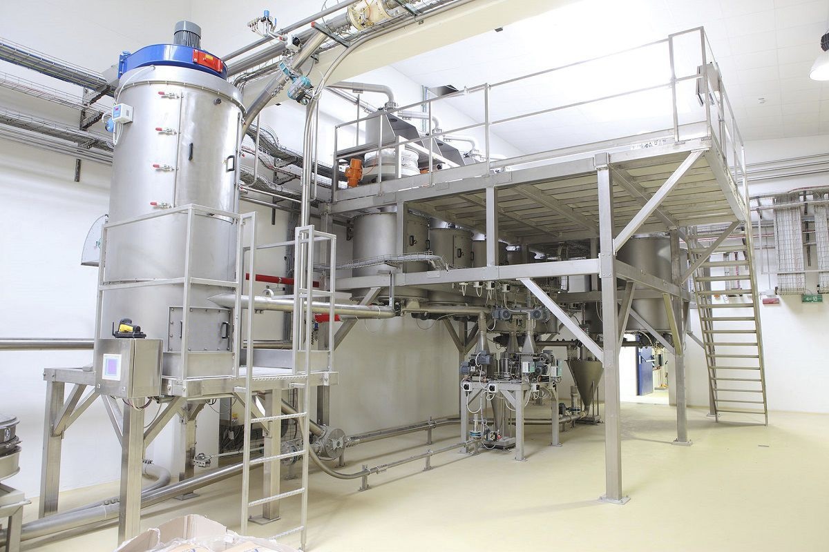
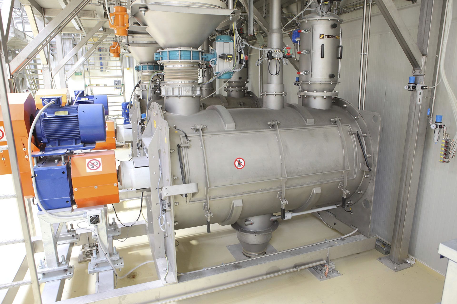
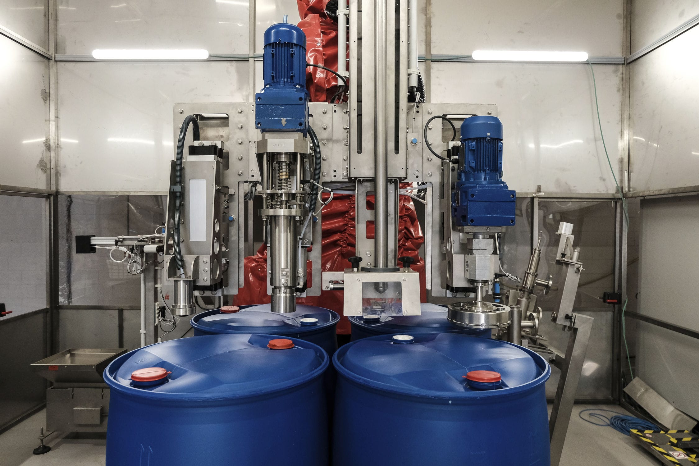
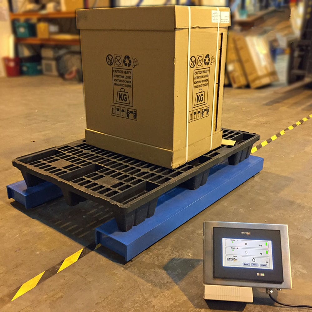


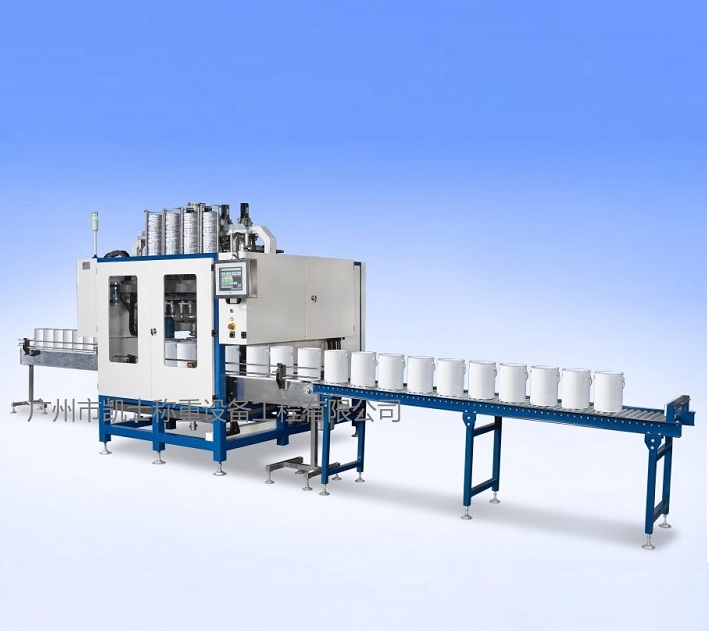
Explosion-proof Liquid filling machine will be sent to the filling position of the empty barrel, the mouth of the barrel and the mouth of the spray gun aligned with the filling machine gun driven by the cylinder into the barrel; liquid filling scale when the detection of the spray gun in place, the bottom valve opens, nitrogen filling valve start to dry nitrogen through the filling port into the barrel, so that the air in the barrel by the nitrogen replacement, and at the same time, can accelerate the drying of the barrel inner wall, to ensure the safety of the filling.

 020-34563445
The weighing and Filling machine creates the operability required for various bottling needs by utilizing the modular nature of all elements of the Electronic scale and selecting the most appropriate inlet valve. The new inlet valve of the Weighing system can be filled with several products on the same production line, fully integrated and interchangeable as part of this new platform. The explosion-proof Liquid filling machine effectively ensures stable operation of the system by using methods such as anti-clogging algorithms, tare weight discrimination, and inlet and outlet counting. The filling process is jointly completed by PLC and weighing instruments, with one weighing instrument corresponding to one scale platform. Before filling, the system automatically determines whether the tare weight value is within the set range. If it is less than the set tare weight value, the instrument does not perform the tare removal operation and does not start the filling process. This function can avoid misfilling due to the barrel not being in place. In order to ensure that the filling barrel is accurately delivered to the nozzle, the stop position of the carriage must be precisely controlled. The speed control of the carriage is achieved by a frequency converter, and properly setting the start and stop times of the frequency converter can make the control of the carriage more accurate and stable. The position of the carriage is detected by a photoelectric switch, which uses the pulse front edge detected by the photoelectric switch as a reference. When one second before the last carriage arrives, the frequency converter is controlled to slow down, allowing the carriage to stop at a more accurate position. After multiple tests, the maximum position error of the carriage is no more than 5mm, usually around 2mm. To ensure that the nozzle enters the barrel opening reliably when it descends, mechanical positioning devices for the barrel opening are installed on both sides of the filling position. The barrel opening positioning device is activated before the nozzle descends, ensuring smooth entry of the nozzle into the barrel.
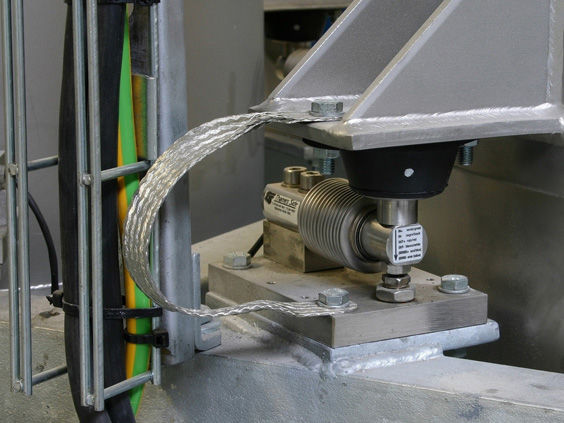
The automatic filling machine adopts a weighing and feeding method, utilizing an oblique tee, valve core, control components, and a filling nozzle tube. The oblique tee consists of a feed inlet, a discharge outlet, and a valve core mounting hole. The discharge outlet is located below the valve core mounting hole, and the feed inlet is set on the side wall between the valve core mounting hole and the discharge outlet. These three components are interconnected. The control components include an actuator and an on-off push rod. The upper end of the on-off push rod is fixedly connected to the actuator, and the valve core is fixed at the lower end of the on-off push rod. The filling nozzle tube is a hollow liquid injection tube, with an external thread on its upper section and a liquid injection nozzle on its lower end. The liquid injection nozzle has a sealing hole inside. After the valve core is pressed into the sealing hole, a reliable sealing structure can be formed. The filling nozzle tube is screwed into the discharge outlet of the oblique tee through the external thread. In the quantitative weighing piston valve device, the motor-driven rotor pump Feeder, which is an electromechanical integrated equipment, is placed between the material silo and the filling valve. The electronic measurement and control device is used to achieve quantitative weighing of the material. When the motor is started, the material in the corresponding material silo enters the hopper filling piston valve along with the conveyance of the rotor pump feeder mechanism. An electronic weighbridge is installed between the hopper and the weighing frame. The weight of the hopper is directly converted into an electrical signal by the weighbridge and sent to the electronic measurement and control device. When the set weight value is reached, the motor is turned off to stop feeding, and the hopper filling valve is controlled to open for unloading, thus completing a quantitative weighing process. To balance the contradiction between weighing accuracy and weighing speed, a two-stage feeding method is adopted. This feeding method can only partially meet the requirements of accuracy and speed. To improve efficiency and solve the problem of out-of-tolerance, a feeding control method of "fast feeding first, then slow feeding, and finally inching" is adopted. The aim is to use "fast feeding" to shorten the feeding time and improve the weighing speed; use "slow feeding" to reduce material impact and improve detection accuracy; and finally use "inching feeding" to ensure the accuracy of the final quantitative weighing by replenishing the material. The control of feeding is set to "fast feeding" at the beginning of weighing, and "slow feeding" starts when the predicted set value of fast feeding is reached; When the predicted time for slow feeding is reached, if the system's allowable error limit for the material's quantitative value is not met, slow "inch feeding" will commence. The hopper door will not be opened for unloading until the net weight of the material exceeds the set value. Since the duration of each inch feeding decreases as the material difference decreases, the occurrence of out-of-tolerance is effectively avoided.
Basic parameters:
Maximum weighing capacity: 30kg
Minimum measurable weight: 0.01kg
Filling error: ±0.01-0.02kg
Filling speed: approximately 1500-1800 barrels per hour for 20L containers
Control mode: 2-gear control
Filling method: insertion type, above the liquid level
Gun head pipeline: Teflon gun head, valve + Teflon hose
Structural material: The main unit is made of SUS304 stainless steel, and the conveyor and palletizing system are coated with anti-corrosion paint made of carbon steel.
Scale platform size: 400×800mm (304 stainless steel powered roller track)
Empty barrel roller track: 400mm×2500mm (304 stainless steel powered roller track) with an additional 1200mm inclined unpowered roller
Heavy barrel roller track: 400mm×2500mm (304 stainless steel powered roller track, 2 sets)
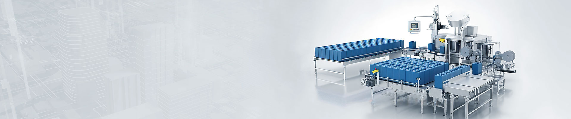
Bucket dividing device: suitable for 20L buckets, constructed with carbon steel anti-corrosion paint and featuring a 304 stainless steel roller track.
Palletizing equipment: Translational type, suitable for pallets 1200×1200×140mm, including pallet supply, palletizing, and unloading conveyor.
Pipeline pressure: 0.2-0.6 MPa (related to material properties).
Material interface: 4 DN40 flange connectors, which can be customized according to the user's interface standards
Air source interface: The user provides a 12mm air tube connector for quick coupling connection
Power supply: AC220/50Hz (provided by the user to the side of the machine)
Air source: 0.4-0.8 MPa (provided by the user to the side of the machine)
Operating temperature: -10℃-50℃
Basic conditions: A level, solid concrete floor with a thickness of more than 10cm.
Optional models: standard type, explosion-proof filling scale