


The Grinding automatic feeder is mainly composed of mechanical part, hydraulic control part and electrical control part. The hydraulic station is assembled on the side of the frame, the electrical control box is installed above the hydraulic station, and the hydraulic control valve group is assembled on the hydraulic station, which is connected to the hydraulic cylinder through the oil pipe, speed regulating valve, diverter valve, etc. Through the programmable logic controller output voltage signal to the corresponding electromagnetic reversing valve and electromagnetic relief valve to realize the oil circuit on and off, control the movement direction of the hydraulic cylinder piston rod.

 020-34563445
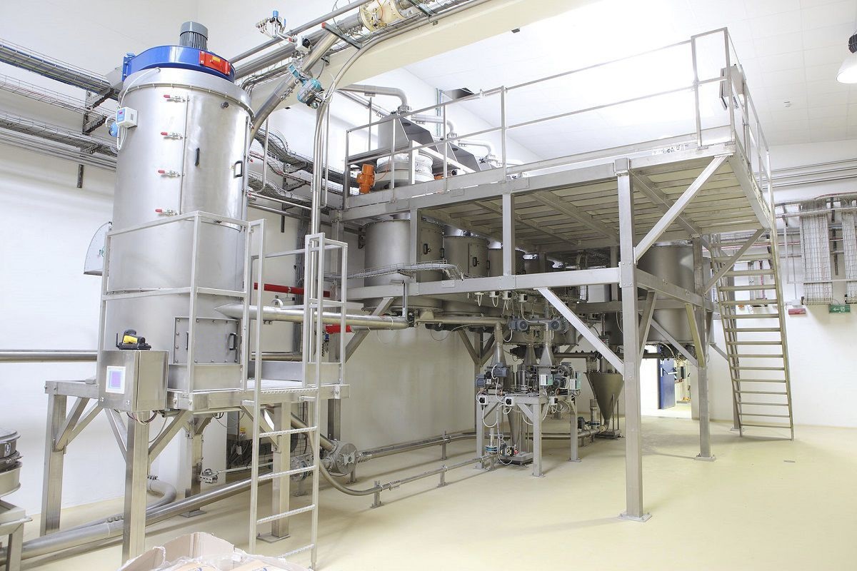
The Grinding automatic Feeder is used to complete the power frequency induction of raw materials to add material, in order to replace the manual skid feeding method, its working principle is: The feedstock is hoisted to the feedstock platform of the reactor with the special crane, the lifting device rises to the upper limit position, the pushing device moves, pushes the raw material about 10cm thick into the kettle, and then returns, the lifting device drops to a certain height and displaces, the pushing device moves for the second time, and so on, until a pile of raw materials are pushed into the kettle, and the lifting device drops to the lower limit position. Stand by for the next cycle. Its control mode has two kinds of manual operation and automatic operation to meet the needs of different production situations.
The automatic feeder is mainly composed of mechanical part, hydraulic control part and electrical control part. The hydraulic station is assembled on the side of the frame, the electrical control box is installed above the hydraulic station, and the hydraulic control valve group is assembled on the hydraulic station, which is connected to the hydraulic cylinder through the oil pipe, speed regulating valve, diverter valve, etc. Through the programmable logic controller output voltage signal to the corresponding electromagnetic reversing valve and electromagnetic relief valve to realize the oil circuit on and off, control the movement direction of the hydraulic cylinder piston rod.
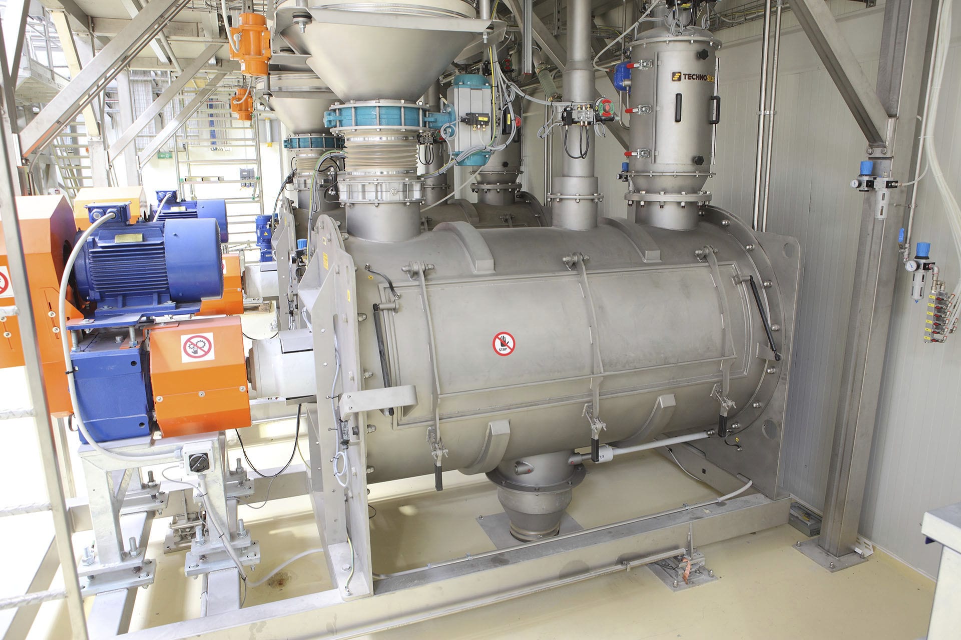
The mechanical part mainly consists of a frame, a lifting device and a pusher device. The lifting device adopts the double mechanism of cylinder drive and chain drive to obtain twice the lifting height with smaller cylinder stroke and reduce the structural size of the automatic feeding unit. The pusher device is fixed in the guide rail of the frame and is fixed on the lifting device by the chain drive. The lifting device drives the pusher device to move up and down in the guide rail to meet the needs of different heights and feed thicknesses of raw materials. The ultimate displacement of the lifting device and the pusher device is regulated by the stroke switch.
The power of the hydraulic station of the automatic feeding unit is 2.2KW, and the pressure, flow and direction of the hydraulic system are all controlled in the hydraulic station. Three actuator hydraulic cylinders are supplied by the vane pump, among which the lifting device has two actuator components. In order to ensure the consistent lifting height and the smooth movement, the shunt valve is used to control. The hydraulic oil flows out through the electromagnetic reversing valve and is evenly distributed through the diverter valve into the lifting hydraulic cylinder, and the pushing device is controlled by a hydraulic cylinder. Each device forms a hydraulic control circuit, when the programmable logic controller outputs the voltage signal to the corresponding electromagnetic reversing valve and electromagnetic relief valve to realize the oil circuit on and off, so as to control the direction of movement of the hydraulic cylinder piston rod.
The electrical control system of the automatic feeder is mainly integrated with Siemens $7-200 YUPLC. In order to realize the control of multiple input and output points, the inductive sensor is used to detect the action position and operating state of each mechanism, and the detection signal is input to the programmable controller, and after automatic processing, the output command signal is sent to the controlled component solenoid valve, and the various mechanisms are moved through the reversing function of the solenoid valve. Through the "state transfer switch" on the control box, the three states of automatic, stop and manual transfer of the pusher can be conveniently and quickly realized. When the unit is abnormal, it can press the emergency stop button or switch to manual shutdown to avoid equipment accidents.
Technical implementation of automatic Feeding machine: Hydraulic drive lifting mechanism lifting cylinder push rod in the vertical direction for reciprocating movement, through the sprocket drive doubling mechanism indirectly drive the pushing mechanism in the vertical direction displacement, to achieve the automatic feeder the tank feed port of raw materials top-down, according to the set displacement and running speed, push material, push plate each push thickness, for lifting cylinder stroke twice; By hydraulically driving the flat pushing cylinder of the pushing mechanism to reciprocate in the horizontal direction, the pushing plate of the automatic feeder can push the raw material into the kettle with a set running speed and a fixed thrust in the horizontal direction.


