


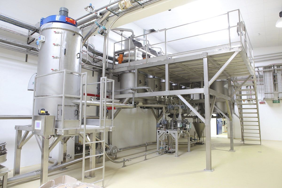


The reduction system is composed of a silo, weighing hopper, impeller feeder, weighing sensor and screw discharge mechanism. It adopts an electronic scale structure to weigh the material. The weighing system bracket, which is made up of a motor, impeller rotor and disc, supports the bearing on the frame. The weighing sensor can accurately sense the weight of the powder on the semi-circular surface. The weight signal and the impeller speed signal are calculated in the microcomputer to obtain the flow signal. After comparison with the set value, it is fed back to the variable speed control motor (including the variable frequency speed control motor of the feeder). By adjusting the speed of the counter weight and the feeder, the powder flow can be regulated.

 020-34563445
The reduction system controls the speed of the discharge screw conveyor based on the rate of weight reduction of the material in the weighing hopper to achieve the purpose of quantitative feeding. When the material in the weighing hopper reaches the lower limit of the weighing, the discharge screw conveyor fixes the discharge volume according to the current speed and simultaneously controls the material in the silo to quickly fall into the weighing hopper. When the material is loaded to the upper limit of the scale, the loading stops. Rapid loading can shorten the feeding time, improve the accuracy of weighing and control precision. Through the fixed-value control of material quantities at each stage, automatic batching control and the collection and transmission of a series of signals are achieved during the production process, thus realizing precise control of feeding.
When the scale is empty, the discharge valve is closed, and the bentonite enters the storage tank through the conveying pipe. The computer displays the total amount of bentonite in the scale. When the weighing quantity exceeds the upper limit set value of the material level, the feeding relay opens and the feeding valve closes. When it is necessary to mix materials, the operator presses the "Start" button with the mouse to control it. The start signal is output, the relay is connected, the valve is opened, and the material is released. When the scale value is greater than the set value, the relay opens, the valve closes, and the discharge stops. After the scale stabilizes, the discharge value is displayed. When the actual weight is less than the set value of the lower limit of the material level, feeding starts again. When feeding for the second time, repeat the above steps.
This reduction system is composed of a silo, weighing hopper, impeller Feeder, weighing sensor and screw discharge mechanism. It adopts an Electronic scale structure to weigh the material. The Weighing system bracket, which is made up of a motor, impeller rotor and disc, supports the bearing on the frame. The electronic scale body is no longer restricted by it. Both the inlet and outlet are connected by flexible connections, which do not affect the force and rotation of the electronic scale body. Ensure the balance on both sides of the electronic scale body. During the powder supply process, due to the rotation of the impeller, the material flows uniformly within the semi-circular area from the feed port to the discharge port. The load cell can precisely sense the weight of the powder on the semi-circular area. The weight signal and the impeller speed signal are calculated in the microcomputer to obtain the flow signal. After comparison with the set value, it is fed back to the variable frequency speed control motor (including the variable frequency speed control motor of the feeder) The powder flow rate can be adjusted by regulating the rotational speed of the weighing machine and the feeder.
The silo and the weighing hopper are closed except for the feed port and the discharge port. The conveying pipes of the feed port and the discharge port are transitionally connected with flexible hoses (hard connection is not allowed, otherwise it will affect the weighing accuracy). Meanwhile, the storage device is covered with insulation material, a limit pull rod with a bearing, and two welded rods for scale calibration. The impeller feeder is connected to the silo. The rotation of the impeller is controlled by the impeller motor. The impeller can be controlled to lower the material into the weighing hopper in both manual and automatic modes.


