


The dense-phase conveying system adopts an intermittent conveying mode and multiple storage pumps working simultaneously. After the storage pumps are put into operation, the feed valve is opened and the material falls into the pump. When the material level gauge sends a full material signal or reaches the set time, the feed valve automatically closes. The intake valve opens, and compressed air enters from the gas chamber at the bottom of the pump body. After diffusion, it passes through the fluidized bed. While the material is fully fluidized, the pressure inside the pump gradually rises. When the pressure inside the pump reaches a certain value, the weighing module sends a signal, the discharge valve opens, the fluidization of the material on the fluidized bed intensifies, and the conveying begins. The material inside the pump gradually decreases. During this process, the material on the fluidized bed is always in a state of fluidization and conveying simultaneously. When the material in the pump has been fully conveyed and the pressure drops to equal to or close to the pipeline resistance, the pressurizing valve and the blow-off valve close. The discharge valve closes after a certain delay, marking the end of the entire process and completing one working cycle.

 020-34563445
The dense-phase conveying system adopts an intermittent conveying mode and multiple storage pumps working simultaneously. Each time the storage pumps enter and exit the material, it is one working cycle. The working process is divided into four stages:
Feeding: After the warehouse pump is put into operation, the feeding valve is opened and the material falls into the pump. When the material level gauge sends a full material signal or reaches the set time, the feed valve automatically closes.
Fluidization: When the intake valve is opened, compressed air enters from the gas chamber at the bottom of the pump body, diffuses and then passes through the fluidized bed. While the material is fully fluidized, the pressure inside the pump gradually rises.
Conveying: When the pressure inside the pump reaches a certain value, the weighing module sends a signal, the discharge valve opens, the fluidization of the material on the fluidized bed intensifies, and conveying begins. The material inside the pump gradually decreases. Throughout this process, the material on the fluidized bed is always in a state of fluidization and conveying simultaneously.
Purging: When the material inside the pump has been fully conveyed and the pressure drops to equal to or close to the pipeline resistance, the pressurizing valve and the blowout valve close. The discharge valve closes after a certain delay, marking the end of the entire process and completing one working cycle.
When transporting in a dense-phase conveying system, the pressure inside the bin pump is constantly changing. During normal operation, during the pressurization stage, the pressure inside the pump rises linearly. During the conveying stage, the pressure inside the pump remains basically unchanged or changes very little. When there is not much material left in the pump or pipeline, the pressure drops rapidly. When it drops to a certain value and remains within a certain range, it then enters the purging stage. In the later stage of purging, the pressure has dropped to a very low value, indicating that the material inside the pipe has been purged clean and the conveying is complete. After the purging stage is completed, the pressure inside the pump remains basically unchanged. At this point, the pressure inside the pump is the resistance that the pipeline has under this steam supply condition. If this value is too large and the material in the pump or pipeline has not been completely conveyed, it will affect the second conveying. If this value is too small, the material inside the pump or pipe will have already been conveyed completely, which will cause waste of compressed air, prolong the conveying time and reduce the conveying efficiency.
The dry ash collected by the electrostatic precipitator is conveyed to the middle silo by two screw conveyors, and then sent into the ash silo through the conveying pipe by the silo pump. After that, it is loaded into the ash tanker by the bulk loader for transportation outside.
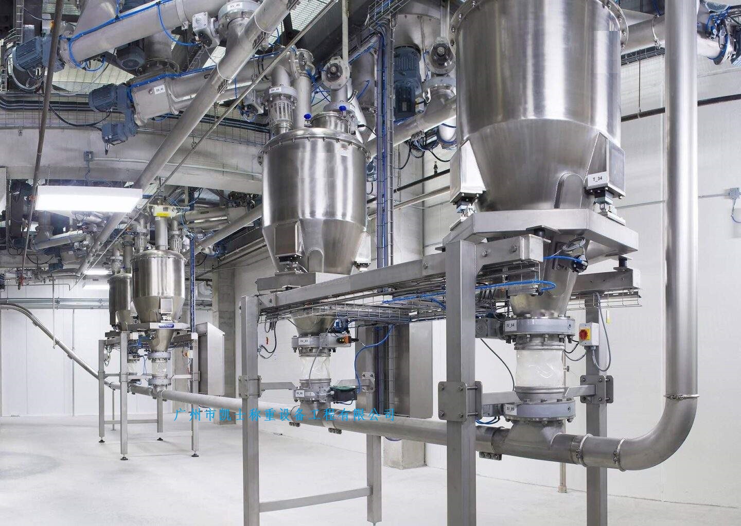
The silo pump is a key piece of equipment in the positive pressure dense-phase pneumatic conveying system, consisting of inlet and outlet valves, pump body, fluidization chamber, air regulating valve, measuring and display instruments, and ash discharge pipe. Fluidization devices and level gauges are key components, and their manufacturing quality and installation techniques should be guaranteed. The cylinders of the inlet and outlet valves should be tightly sealed, and the transmission should be unobstructed.
The middle bin is connected to the ash drop pipes of the two screw conveyors under the ash hopper of the dust collector at the top and to the two bin pumps at the bottom through the feed 阌. To ensure the smooth feeding and effective volume of the middle silo, a residual gas discharge pipe is installed at its top, which discharges the remaining gas into the inlet flue of the dust collector. The inner diameter of the exhaust pipe should be around 100mm, and it should be arranged gently, short and straight.
Each tank is equipped with two storage pumps that share one material conveying pipe. The horizontal length is 70 meters, the conveying height is 20 meters, and the pipe diameter is DN80mm. The installation requirements for the material conveying pipe are as follows: the bending radius of the pipe's curved part should be greater than 700mm, and the material of the elbow should be steel-ceramic composite pipe to reduce wear and maintenance workload. A pair of flanges should be installed every 15 to 20 meters between pipelines to facilitate disassembly and maintenance. After the pipes and valves are installed, a gas tightness test should be conducted, and any remaining debris or rust should be blown and brushed clean. Finally, the main equipment can be installed.
The inclination Angle of the ash silo and the ash unloading equipment at the conical part of the ash silo is 30°-35 ", and three fluidizing plates are evenly distributed around it to prevent dry ash from caking and facilitate purging. The top of the ash silo is equipped with a bag filter. When the dry ash and air mixture enter the upper part of the ash silo, they are expanded, depressurized and decelerated. The dry ash falls into the ash silo, while the separated air is filtered by the bag filter and then discharged into the atmosphere.
The compressed air required for the conveying in the pneumatic conveying system and the pneumatic devices in the control system is supplied by the air source system. The main equipment in the air source system includes screw air compressors, dryers, air filters, wet and dry air storage tanks, etc. To prepare clean and dry compressed air, in addition to the equipment quality meeting the requirements, during the installation process, first, it is necessary to ensure that the air compressor has sufficient cooling water, and second, the drainage (oil) from the dryer and filter should be discharged in a timely manner. It should be particularly noted that if the compressed air contains water, it will cause the silo pump and the material conveying pipeline to stick and get clogged with ash. In severe cases, it may lead to pipe blockage or damage to the pneumatic device, forcing the system to shut down.
The dense-phase conveying system adopts a conveying method that combines PLC programmable controllers with local manual operation. The ash discharge of the PLC can be controlled by the material level. When the material level gauge of the silo pump detects the set value of the ash level, the material feeding begins. It can also be controlled by time. Within the set time, regardless of the ash level of the silo pump, one conveying cycle is carried out. The material conveying system is also set with an alarm signal. When the gas pressure is insufficient and fails to reach the set 0.6MPa; Or if the feeding time exceeds the preset 3.5 minutes: when the conveying pressure of the warehouse pump fails to reach 1.15 to 0.06MPa, the system will trigger an alarm. Some systems are also equipped with an alarm for the limit height of the ash silo. When the material level reaches the set height, an alarm signal will be sent out and the entire system will cease operation.
The local control mode is to configure a valve control box locally for each warehouse pump. The operator can operate each valve through the switches on the control box. Manual operation must be carried out when the working mode of the warehouse pump is all in the "exit" position. Only then can the knob be turned to the manual position to perform manual operations such as feeding, pressurization, auxiliary blowing, and material feeding.


