






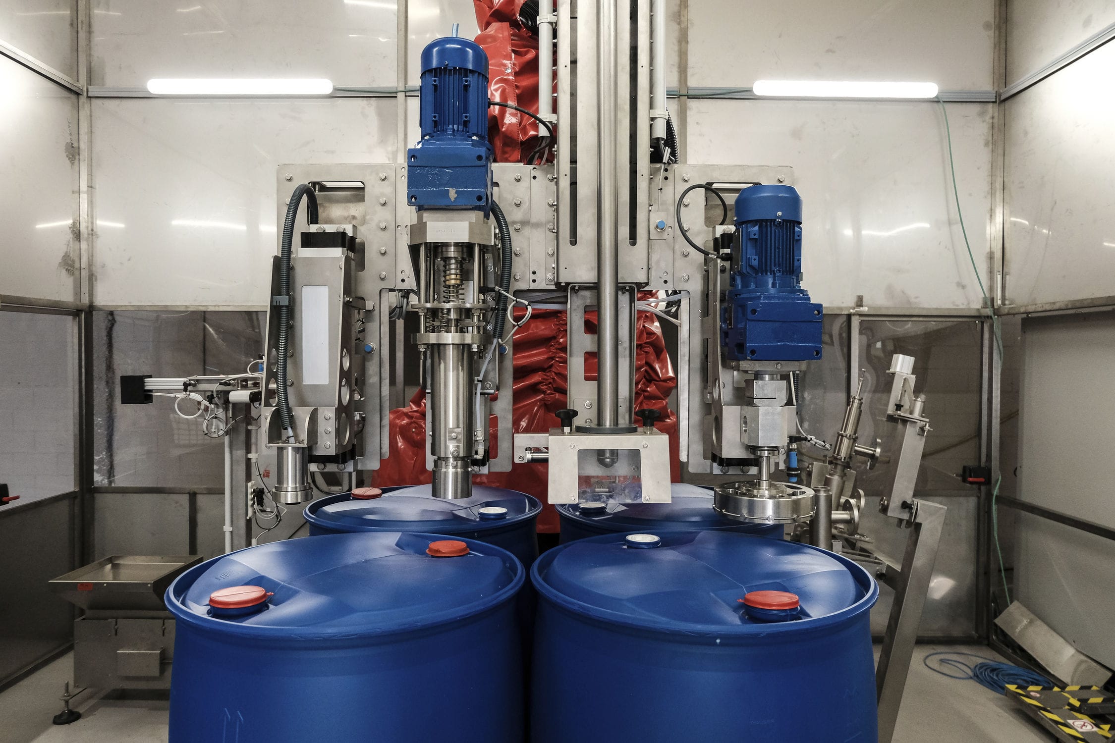
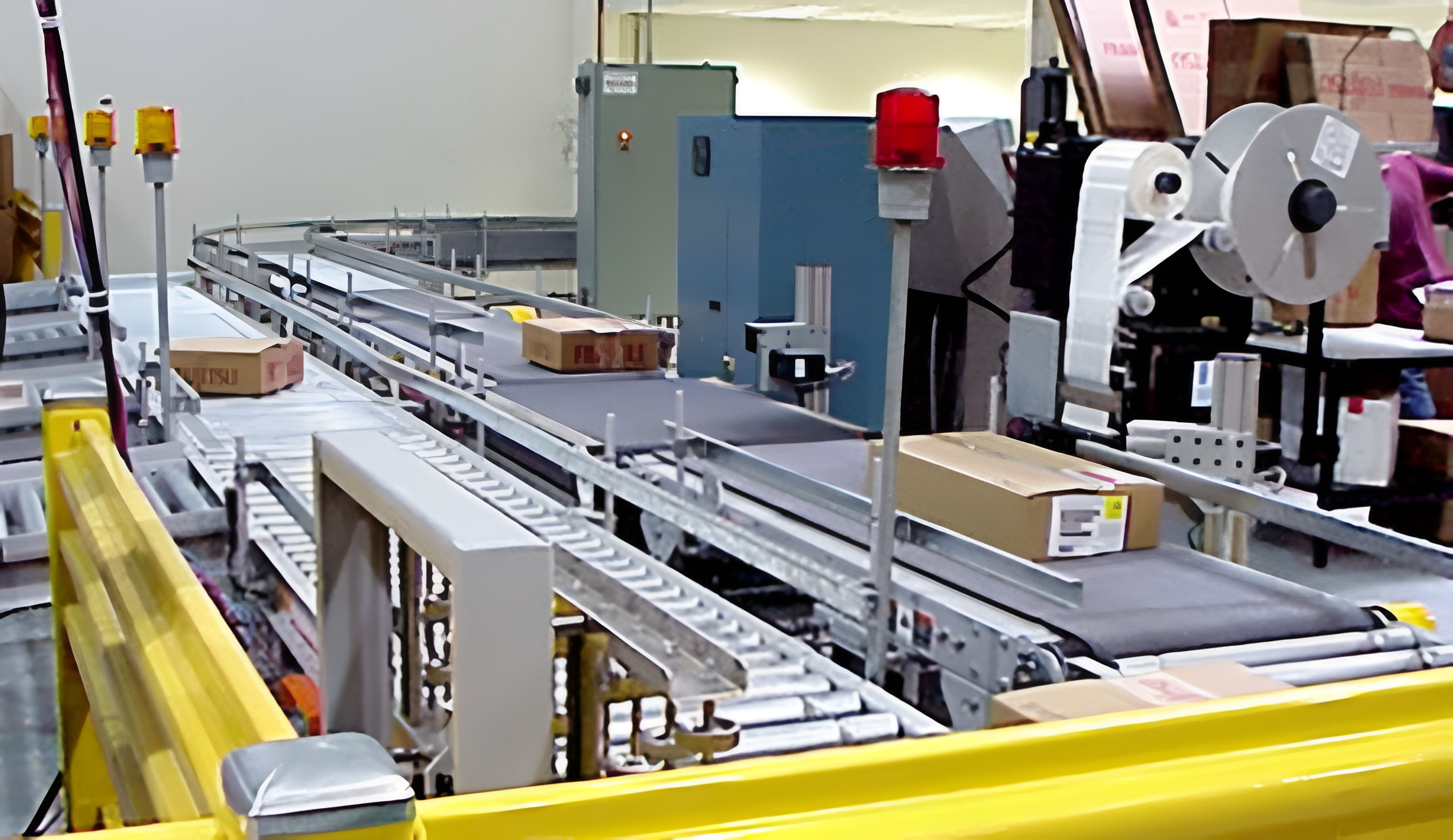
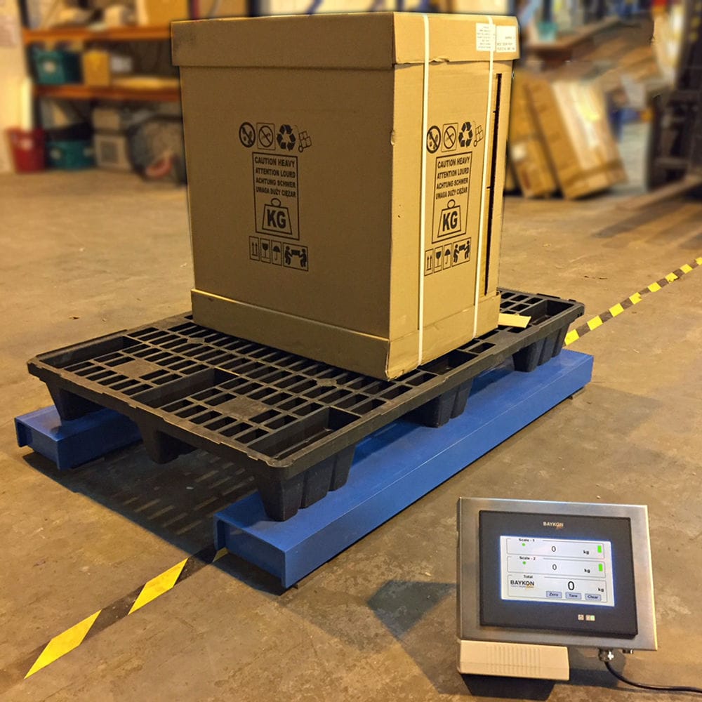


The microcomputer hopper scale is displayed through the human-machine interface touch screen. The operator can directly see the material quantity in the silo from the driver's cab. Meanwhile, the touch screen is equipped with manual and automatic receiving and loading operation modes, and the signals of each material level participate in interlocking. The high material level is the upper limit for receiving materials. After the PLC receives the high material level signal, it automatically controls the electro-hydraulic push rod to close the hopper leak and controls the solenoid valve to stop the hopper from vibrating materials.

 020-34563445
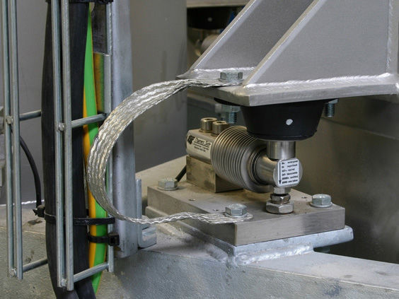
In the production process of the power plant, the metering microcomputer system communicates with the weighing instrument and the computer through the signals of the switch quantity of the screw Feeder and the motor, establishing and realizing the system on the computer. By using advanced dynamic weighing instruments, the speed signal and weighing signal of the screw can be accurately collected, and then processed by internal calculus to obtain precise measurement data. The upper computer and the instrument obtain the continuous flow data of the screw weighing in real time through the serial communication interface (RS-232/RS-485/RS-422). The weighing module of the hopper scale supports the weighing point, and the measuring funnel utilizes the reasonable layout of the weighing module to generate a force balance. By changing the position of the support point, the weighing funnel is balanced. In the existing on-site conditions, the position of the weighing module of the measuring funnel is shifted to the front end of the hopper through measurement and calculation, so that all the force points of the hopper are between the centers of the support points of all the Weighing modules, and the distance between the support points and the force points is maximized. That is, a triangular frame made of 16-gauge channel steel is welded on the left side of the steel column at the front end of the hopper, and a cement crossbeam 200mm wide and 500mm high on the ground is used on the right side. It has been certified to be able to withstand the required load. A frame and a triangular frame made of 16-gauge and 20-gauge channel steel are suspended between them, and a 2-meter-long square steel crossbeam made of 16-gauge channel steel is installed on the frame and the triangular frame, and welded firmly. At the front part of the measuring funnel, two thick 12mm steel plates made of 16-gauge channel steel are welded and used as a base plate for the weighing module, and the weighing module is installed between the triangular frame and the crossbeam of the hopper body, so that the hopper can be stably supported on the four weighing modules, ensuring the accurate measurement and the stability of material feeding.
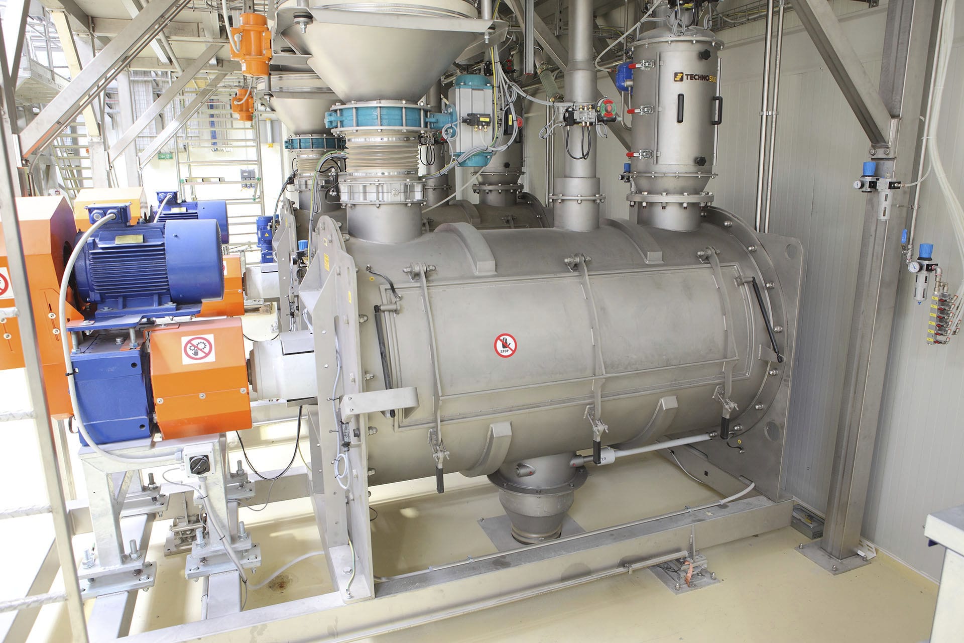
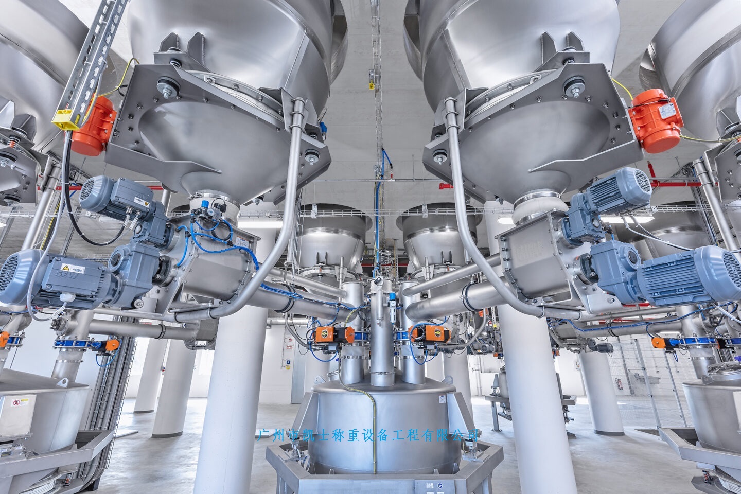
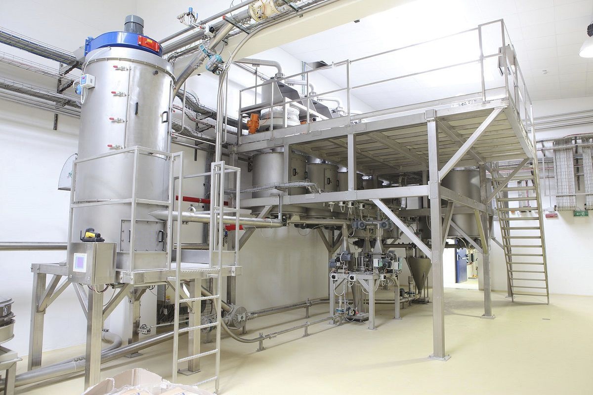
The hopper scale adopts a receiving bin. The bottom of the receiving bin is fixedly connected to a receiving hopper. The bottom of the receiving hopper is equipped with a discharge port, and a discharge valve is set on the discharge port to control the opening and closing of the discharge port. The top of the receiving bin is equipped with a weighing Feeding machine. The weighing feeding machine can transport the main material from the main material storage tank to the receiving bin. The receiving bin is supported and installed on the frame, and at least two weighing modules are set between the receiving bin and the frame. The hopper scale feeds the receiving bin through the weighing feeding machine. The entire process is efficient, fast, and dust-free. After the material is fed in the receiving bin, the weighing module can transfer the mass of the main material in the receiving bin to the controller, thereby achieving the automatic measurement of the main material mass in the receiving bin. The weighing feeding machine is arranged from top to bottom with a storage hopper and a weighing hopper. The lower end of the storage hopper is equipped with a discharge bin, and on both sides of the discharge bin, there are two sets of sliding valves. The sliding valves pass through one end of the side wall of the discharge bin and are connected to a cylinder. The discharge bin also has a locking device for the sliding valves, which includes two sets of slots. The front and rear ends of the slots are fixedly connected to the inner wall of the discharge bin, and an iron plate is installed on the inner surface of the slot. Below the sliding valves, there is an adapter slot for the iron plate. The inner top wall of the slot is equipped with an electromagnet. When the two sliding valves are closed, the distance from the slot to the center axis of the discharge bin is greater than the distance from the slot to the center axis of the discharge bin. In the early stage of weighing, the discharge aperture of the discharge bin is large to facilitate the discharge speed, and in the later stage of weighing, the discharge aperture of the discharge bin is small to facilitate the control of weighing accuracy, ensuring the weighing accuracy and speed, and improving the production efficiency.
Each time the loading vehicle fills one cell of the material level chamber, it needs to weigh the material level chamber on the hopper. Assuming the weighing result is y tons, subtract y tons from the measured value x tons when receiving the material, which is the loading volume of one material level chamber. This difference can be used as the actual loading volume feedback value and transmitted through the isolation relay to the loading vehicle PLC to dynamically correct the high, medium, and low material levels until the average loading volume of the material level chamber reaches the process requirements. Three 350Ω resistive strain gauge weighing modules are symmetrically installed on each hopper. The weighing modules are press-fit type, that is, the loading hopper is supported by four weighing sensors. The weighing sensors obtain the bridge excitation power supply through the junction box, and the signals of the four weighing sensors are superimposed in the junction box and input to the analog/digital unit for analog/digital conversion (the bridge excitation power supply and the analog/digital converter are all included in the weighing instrument). The weighing instrument simultaneously transmits the weight value as a standard 4-20mA current signal to the PLC and displays it on the touch screen in the driver's cab. The loading vehicle runs on the loading vehicle track at the bottom of the hopper scale. Its function is to take material from the hopper, measure it, and then load it into the material level chamber. At the same time, the flue gas overflowing from the loading hole during the loading process is collected and mixed with an appropriate amount of air and introduced into the fixed dust collection pipe. In the lower part of each loading hopper, there are electric motor-driven spiral feeders, which are driven by an activity guide sleeve to load the material into the material level chamber. The total volume of the hopper is suitable for loading by four loading hoppers simultaneously. The hopper is equipped with a resistive material level sensor, which can display the highest point, lowest point, and even material level of the material line. On the upper part of each hopper, there is an adjustable height movable receiving grate (the adjustable range is greater than 100mm), which can intercept large particles or clumps of material flowing out from the hopper during loading. When the hopper receives material, the driver can control the opening and vibration of the hopper's vent on the vehicle. When the material is loaded to the position of each mechanical movable stop block, the limit switch sends low, medium, and high material level signals to the PLC, which are displayed on the human-machine interface touch screen. The operator can visually see the material volume in the silo in the driver's cab, and the touch screen also has manual and automatic receiving and loading operation modes, and each material level signal participates in the interlock. The high material level is the upper limit of material reception. When the PLC receives the high material level signal, it automatically controls the electro-hydraulic push rod to close the hopper vent and controls the solenoid valve to stop the hopper vibration. The medium material level is the even material level. When the material level chamber is filled to the medium material level, the PLC control system sends a level adjustment signal to the pusher vehicle, and the pusher vehicle starts to level the material. The low material level is the lower limit of material loading. When the PLC receives the low material level signal, it automatically stops the spiral feeder device, closes the feeding gate plate, covers the tank cover, and retracts the guide sleeve device and the flue gas exhaust mechanism.