


The hopper screw scale is composed of an upper computer, PLC, instruments and a frequency converter. The PLC adopts Siemens S7-300 and exchanges data with the upper computer via industrial Ethernet. The detection instruments and actuating elements are directly connected to the I/ O module of the PLC. The entire line is controlled by PLC programs. Programming uses ladder diagrams and is uniformly programmed in combination with the external characteristics of the controlled electrical system to achieve sequential control, logical control, interlocking and interlocking. Manual and automatic operation modes can be switched.

 020-34563445
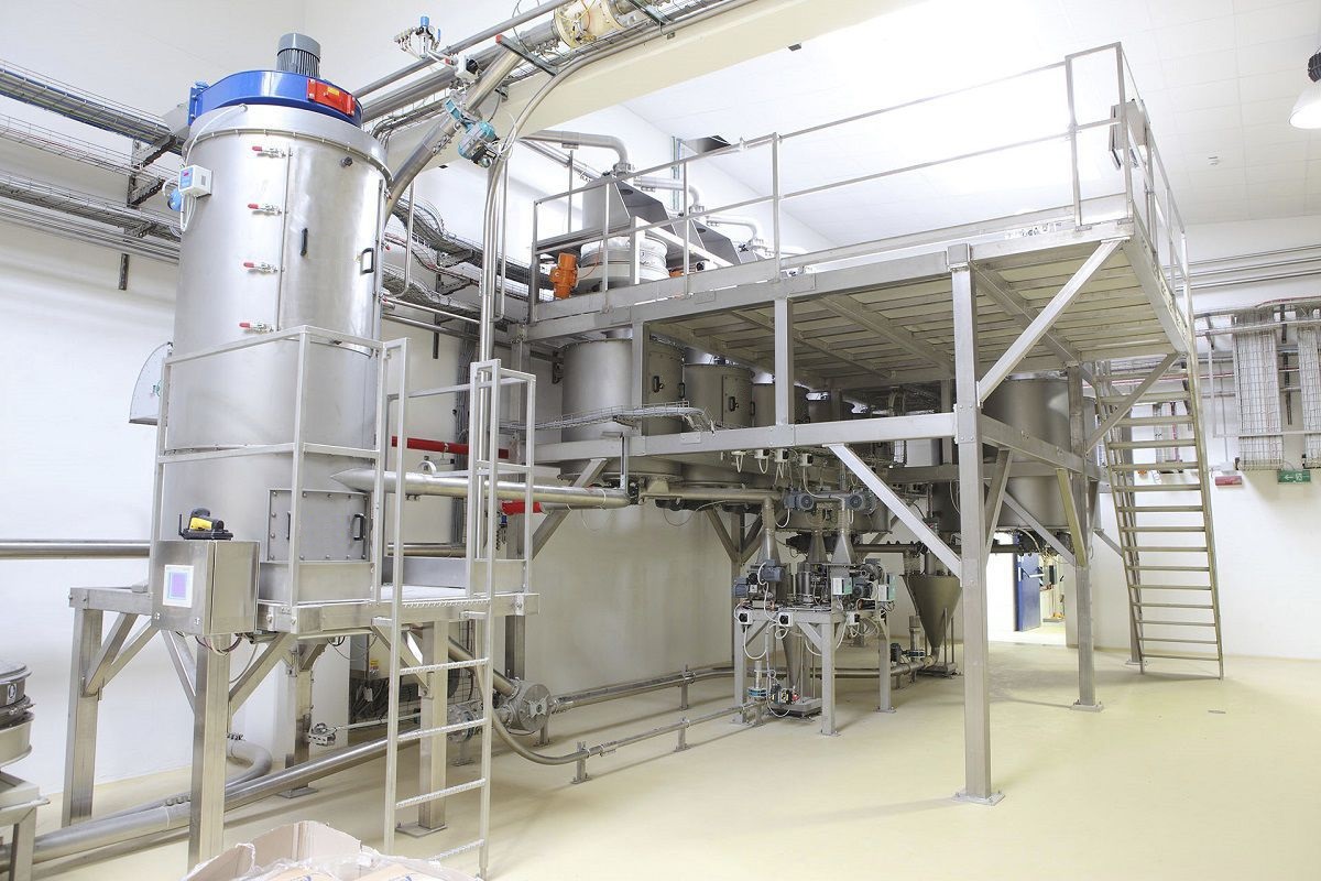
The hopper spiral scale is mainly composed of a hopper, a spiral Feeder, and a weighing hopper. The materials are fixedly stored in the hopper in sequence, and then the materials are sent to the weighing hopper through the spiral feeder. The weighing module is installed at the bottom of the weighing hopper to detect the weight of the materials. After the materials are discharged from the weighing hopper, they are sent to the transfer hopper through the summary hopper to complete the entire feeding function. The hopper scale includes a hopper, a breaker, a spiral conveyor, a housing, and an outfeed hopper. A breaker is set below the hopper, and a spiral conveyor is set below the breaker. The breaker and the spiral conveyor are installed on the housing. A discharge hopper is installed at the end of the spiral conveyor. Two legs are set on each side of the hopper, and each leg has a weighing sensor at the lower part. On the left and right sides of the hopper, there is an air hammer on each side. The materials can be fed according to the required feeding weight. The breaker can prevent the powder materials from becoming compacted, ensuring that the materials can be fully mixed. By adjusting the rotational speed of the spiral conveyor, a feeding quantity signal is given. The PLC analyzes and processes this signal to obtain the set speed signal for the feeding screw, and controls the frequency converter to output a certain frequency to make the motor run at the set speed, achieving the transportation of materials. The hardware structure of the Feeding machine includes weighing sensors, speed sensors, etc. The control system receives the feedback signals from various sensors and calculates and processes them to obtain the actual feeding quantity value. By comparing the deviation between the set feeding quantity and the actual feeding quantity, the feeding machine transportation speed is adjusted in real time, and the actual feeding quantity is controlled within a reasonable range.
The spiral feeder transports the piled materials from the coarse feeding hopper and delivers them to the weighing hopper. The two weighing hoppers on the upper and lower parts of the weighing hopper perform interlocking and closing at a certain frequency. 90% of the predetermined weight of the materials is separated by the weighing hopper. Then, the spiral feeder feeds the separated materials to the Electronic scale, which accurately weighs the materials and sends a signal to the control element. The control element receives the signal, analyzes it, and then sends a control signal to the fine feeding mechanism to send the remaining weight of the materials to the weighing hopper of the electronic scale. During the transportation process, the electronic scale dynamically weighs the materials in the weighing hopper and sends a signal to the control element. When the weight of the materials in the weighing hopper reaches the predetermined weight, the control element sends a signal to the motor of the control screw, which drives the screw to push the materials in the weighing hopper to the moving cart of the hopper.
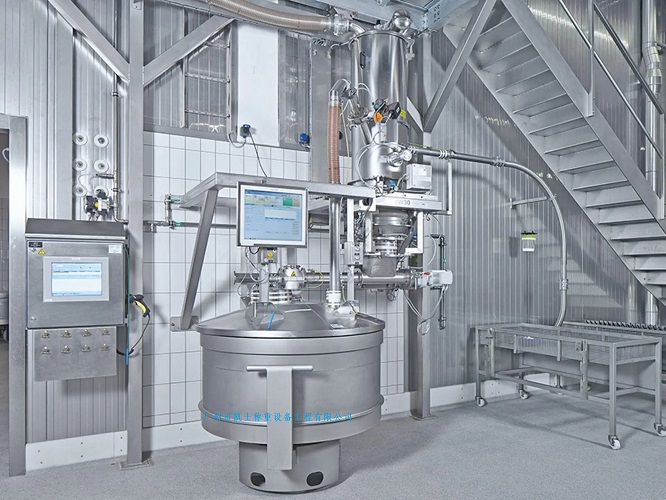
The weighing hopper system is composed of an upper computer, PLC, instruments, and frequency converters. It is unified programmed based on the external characteristics of the controlled electrical equipment to achieve sequential control, logical control, linkage, and interlock. Manual and automatic operation modes can be switched. It communicates with the upper computer through the RS485 bus to achieve upper computer monitoring of multiple systems. The weighing module can control external devices such as the spiral conveyor, the material door switch, and the printer. It adopts advanced control technology and has an intelligent Weighing system. It is composed of a variable pitch spiral conveyor, a cylindrical material storage bin, and a drive motor. According to the variable pitch spiral conveyor, it is mainly composed of a dense spiral, a wide spiral, and an inverted spiral. To prevent high-viscosity materials from blocking the material storage bin and to ensure the smooth discharge of volatile substances from the material storage bin, the pitch and total length should be ensured to be long enough. At the same time, it provides sufficient space for heated expansion materials and pyrolysis volatile substances, allowing the materials to be pyrolyzed through the wide spiral as much as possible, and most of them directly fall into the material storage bin. The reverse spiral transports the remaining weight of the materials from the end of the material storage bin to the mixer to avoid settling at the end, which is beneficial for the quantitative quantification of the entire reaction for solid products. It also prevents particles from blocking the bearings, ensuring the stable and continuous operation of the spiral conveyor for a long time.


