




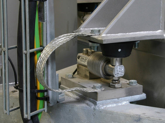
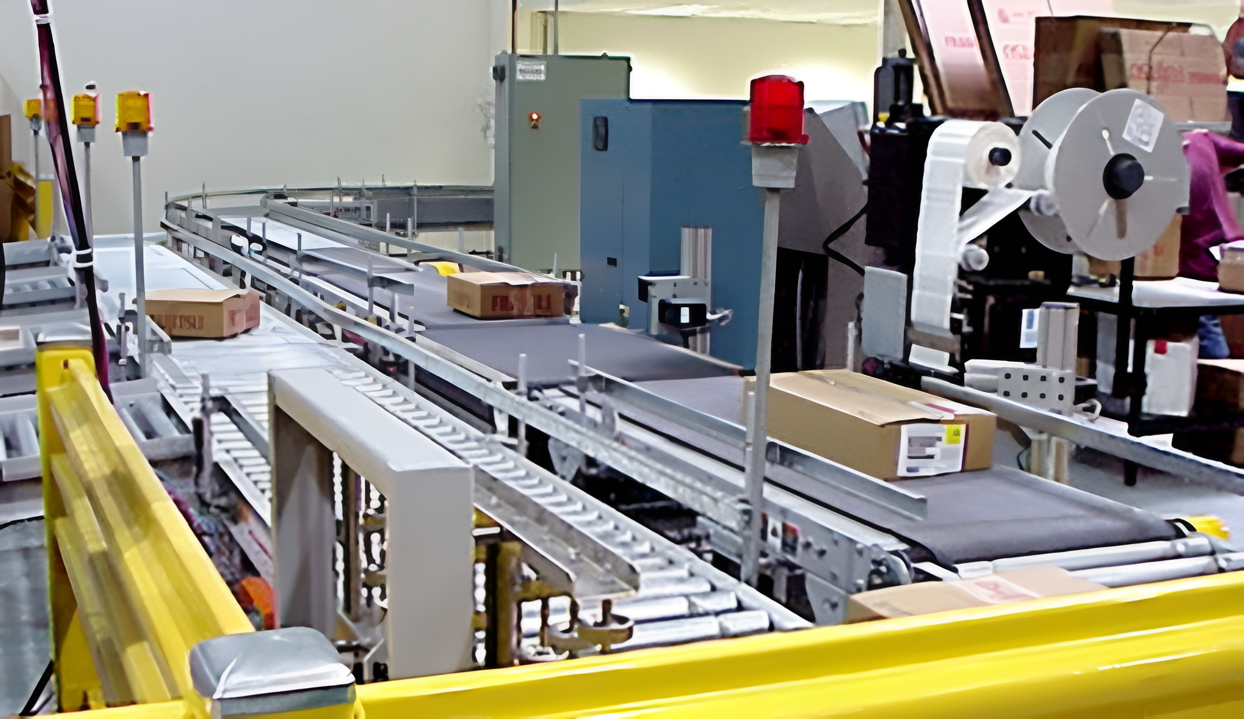
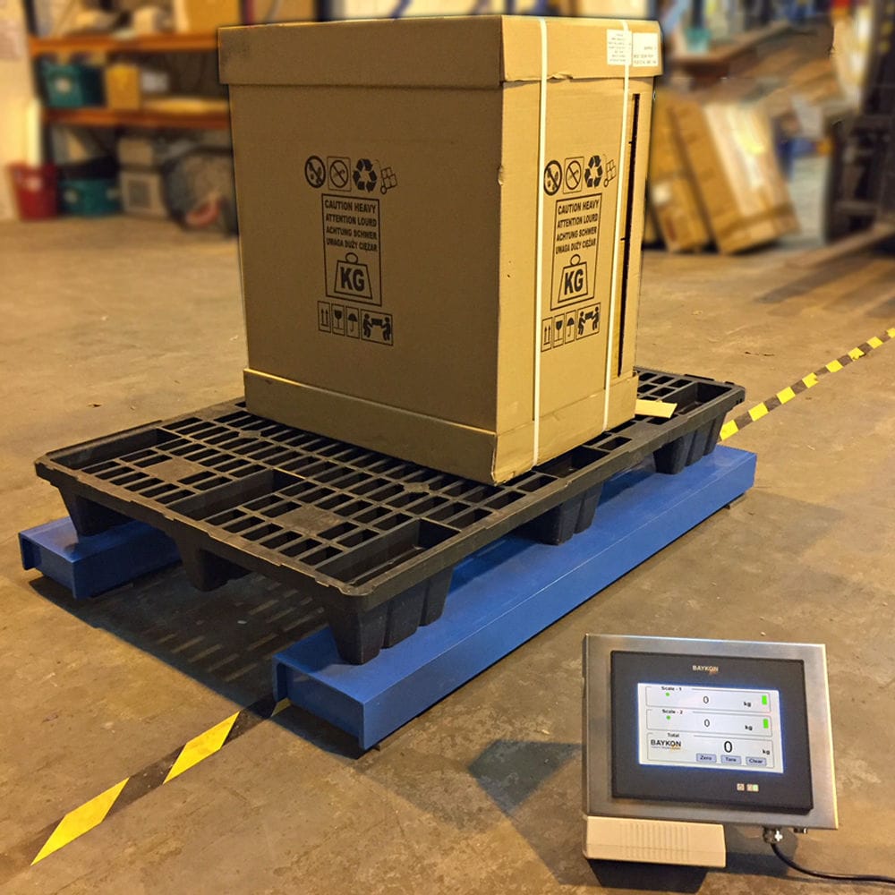


The hydraulic cylinder scale uses four balanced hydraulic cylinders for downward force application. The four main lifting cylinders in the middle lift the sliding block at the upper part of the hydraulic cylinder. Due to the interference fit between the sliding block and the main structure of the scale, after lifting, it acts as a whole. Thus, the lateral gravity is transferred to the main structure, without damaging the weighing module components and the hydraulic cylinder. The side lifting cylinders are raised during weighing to allow the weighing module to bear the pressure and sense the weight value. When it is not necessary to weigh, the support leg cylinders are retracted to prevent the weighing module from bearing weight.

 020-34563445
The hydraulic scale of the cylinder adopts a small vehicle hydraulic Weighing system, including the weighing module, the leg hydraulic cylinders, and the weighing instrument. The data connection between the weighing module and the weighing instrument is established. The weighing module is placed at the lower part of the small vehicle's cargo box, and the leg hydraulic cylinders are connected to the weighing module and set between the weighing module and the ground. When the small vehicle starts to load, the leg hydraulic cylinders extend first to support the small vehicle until the tires leave the ground. Only the leg hydraulic cylinders support the weighing module, ensuring that the entire load of the small vehicle is on the weighing module. The leg hydraulic cylinders and the weighing module are set in a component-matched configuration, usually four such components are set on the small vehicle, with four each on the front and rear of the cargo box. As the goods are loaded or unloaded, the weight of the small vehicle changes continuously. The control display module promptly displays the changes in weight. When loading or unloading is completed, the hydraulic weighing system of the small vehicle retracts, and the leg hydraulic cylinders retract.
The bottom of the center of the scale is equipped with four hydraulic cylinders. Before feeding materials, the hydraulic cylinders operate to transfer the gravitational force of the scale platform to the base, which is borne by the four hydraulic cylinder pistons at the four ends of the scale. There are four oil cylinders in the central position, which are at a certain distance from the ground. Four balanced oil cylinders are used to bear the force, and the four main lifting oil cylinders lift the upper slider of the oil cylinder. Due to the interference fit between the slider and the weighing main structure, after lifting, it is equivalent to a whole, thus the lateral force is transmitted to the main structure without damaging the weighing module and the oil cylinders. The side lifting oil cylinders are raised during weighing to allow the weighing module to bear the pressure and sense the weight value. When it is necessary to stop weighing, the leg hydraulic cylinders are retracted, and the weighing module does not bear the weight.
The oil circuit is used in the entire production system of the Electronic scale. The electronic scale is designed as a part of the production system, and the process shares a hydraulic system. The scale is a part of the production system, and on the oil circuit, the oil pump supplies oil, the accumulator stores energy, and the filter filters the oil, etc., all using the oil circuit of the entire production system. The weighing part is connected to the system through four oil pipes, P for supplying oil and 0 for returning oil. When the oil flows from the P pipe to the upper oil cylinders, it acts as a single-way valve, and there is no backflow of the oil, so even if due to the action of the spring, it will not cause the mechanical performance of the lifting to become soft. When it is necessary to return the oil, it acts as a throttle valve, adjusting the opening degree of the throttle port by adjusting the position of the regulating rod to regulate the flow rate. The electromagnetic directional valve operates when feeding materials, the right position of the valve is in the working position, the oil flows upward from the P pipe into the oil cylinder, overcoming the resistance of the spring, and lifts upward. After the feeding is completed, the electromagnetic coil is energized, the left position is in the working position, the oil in the oil cylinder returns through the 0 pipe, and the lifting rod of the oil cylinder lowers.
The leg hydraulic scale uses the side lifting part hydraulic system to protect the measuring elements of the scale weighing. Before lifting the platform for weighing, it is to allow the weighing module to bear the weight. When it is not weighing, the leg hydraulic cylinders are retracted, and the leg hydraulic cylinders do not feel the weight of the object. The oil cylinder mainly lifts the weighing platform upward. The two-position two-way valve can switch between bidirectional and single-direction flow. When it is switched to single-direction, it acts as a single-way valve and maintains pressure. The pilot-type pressure reducing valve mainly functions to maintain a set constant pressure after the pressure flows through the pipeline P, ensuring the stable operation of the actuator. The throttle valve when the liquid flows upward can adjust the flow rate by adjusting the position of the regulating rod; when the liquid flows downward, it becomes a single-way valve, and the liquid can smoothly pass through the throttle valve. The three-position four-way electromagnetic directional valve when the electromagnetic valve is energized and attracted, the left position is in the working position, the oil flows into the upper oil chamber of the oil cylinder through four ports, while the oil in the lower oil chamber returns through the 0 pipe, and the oil rod drops rapidly, mainly completing the function of quickly lowering the scale platform during measurement. When the solenoid valves are both de-energized simultaneously, the directional valve is in the middle position, the P pipe is sealed, and the oil in the upper and lower oil chambers can flow through the four ports into the 0 pipe. At this time, the actuating element floats and can move under the action of external force. If there is a weighing object at this time, the weighing platform will not fall back and the weighing element can be used for weighing. If the solenoid valve is energized and engages, the right position is in the working position, the four ports are connected to the P port, and the 0 port is sealed. Oil is supplied from the P port to the upper and lower four oil chambers, forming a differential oil circuit. Due to the differential effect, the oil rod rises rapidly. The design of the differential oil circuit is mainly to improve the speed of the action. The right position is used before loading or unloading to quickly raise the platform to allow the weighing module to bear the load. The weighing instrument will promptly display the change in weight. When loading or unloading is completed, the hydraulic weighing system of the trolley retracts the structure and the leg oil cylinders retract.