


The automatic double-scale hopper machine mainly consists of the feeding part, weighing part, loading part and conveying part. The feeding section is responsible for transporting the finished materials to be weighed by the conveying equipment. The weighing section uses A dual-metering electronic scale for finished product weighing. The A and B scale oscillators feed materials to the scale hoppers of the A and B scales to measure the weight of the materials.

 020-34563445
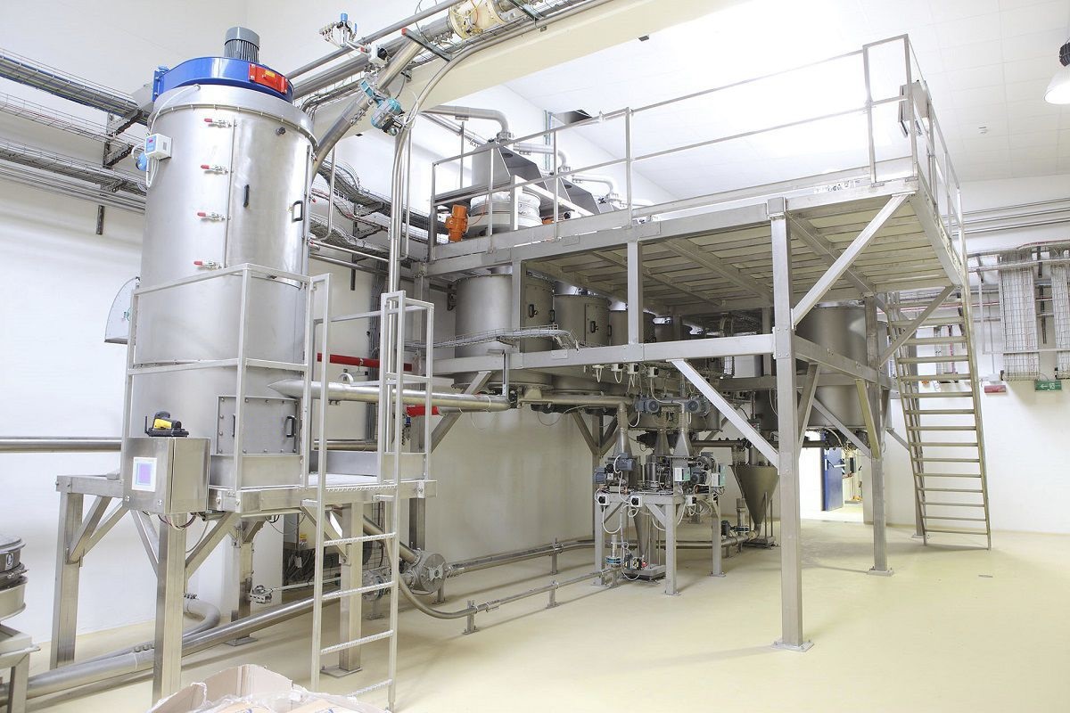
The automatic double-scale hopper machine mainly consists of the feeding part, weighing part, loading part and conveying part. The feeding section is responsible for transporting the finished materials to be weighed by the conveying equipment. The weighing section uses A dual-metering Electronic scale for finished product weighing. The A and B scale oscillators feed materials to the scale hoppers of the A and B scales to measure the weight of the materials. The loading section is the process of loading finished materials of standard weight. The conveying section is used to weigh the finished materials through the conveying equipment and transport the loaded materials away by the conveyor. The weighing instrument is controlled by PLC as the control core. By collecting and processing the detected signals, it sends control signals to various control units. The feeding screw releases the materials into the weighing hopper, causing the weight of the weighing hopper to change. This change causes the voltage signal output by the weighing module to vary. The voltage signal enters the weighing instrument, undergoes A/D conversion, and converts the analog quantity into a digital quantity for display. It communicates with the PLC via the RS232 interface, sending this digital quantity to the PLC. Through the I/ O board control, the switch quantity is sent to the PLC unit. Meanwhile, the hopper scale compares this weight with the set value in the weighing instrument. When the set weight is reached, a switch signal is output to the PLC. The PLC controls the frequency converter to gradually reduce the speed, calmly achieving slow feeding. When the set completed weight is reached, the motor stops rotating, thereby achieving the allocation of a certain material.
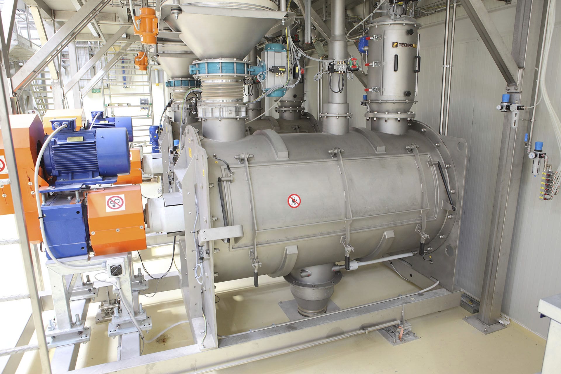
When feeding the automatic double-scale hopper machine, coarse materials are fed first, and the system adopts closed-loop control. When the given weight does not reach 95% of the rated quantity, the coarse material inlet valve remains open and the feeding speed is relatively fast. When the weight reaches 95%, the weighing module sends a signal, and then the coarse material inlet valve is closed through the actuator. At this point, the fine material inlet valve automatically opens. When the weight reaches the rated value, the fine material valve closes and the weighing is completed.
When the conveying equipment delivers the finished material, the oscillators of Scale A and Scale B start to swing, and the oscillator baffle opens. When the maximum feeding weight is reached, the baffle closes and the small oscillation feeding begins. When the preset weight is reached, the feeding stops, the scale hopper opens, and the material is discharged through the transition hopper, completing one packaging cycle. The Weighing system control device adopts contactless detection control. The contactless detection and control device applies differential transformers, photosensitive components and electronic device detection sensors to detect and control the pre-determined weighing program of the weighing system, obtaining corresponding signals. After being amplified by the electronic device, it automatically controls the actuator to perform weighing work according to the required program.
The double scale hoppers of the weighing control system are equipped with reflective photoelectric detection switches. Selecting ordinary photoelectric detection switches can fully meet the requirements of the control system. The modulated pulses generated by the oscillation circuit are reflected by the reflective circuit and then radiated by the light-emitting tubes as light pulses. When the object under test enters the operating range of the light receiver, the reflected light pulse enters the phototransistor. In the receiving circuit, the optical pulse is demodulated into an electrical pulse signal, which is then amplified by an amplifier and synchronously selected and shaped. Subsequently, interference is eliminated through digital integration or integration methods. Finally, after a delay (or no delay), the drive output photoelectric switch control signal is triggered.


