


The PLC regulation system adopted by the automatic reaction vessel weighing system is based on the controlled object of the batching machine, with the input specifications being the real-time mass of the batching components. The multi-level variable-speed batching controller, based on the deviation between the input and feedback, controls the rotational speed and corresponding time of the batching machine according to the set batching parameters (the rotational speed of the batching machine and the corresponding time), thereby controlling the output quality of the batching machine. If the parameter settings are appropriate, within the set error range. Once the formula changes or the rotational speed of the feeder changes, the batching parameters need to be adjusted significantly.

 020-34563445
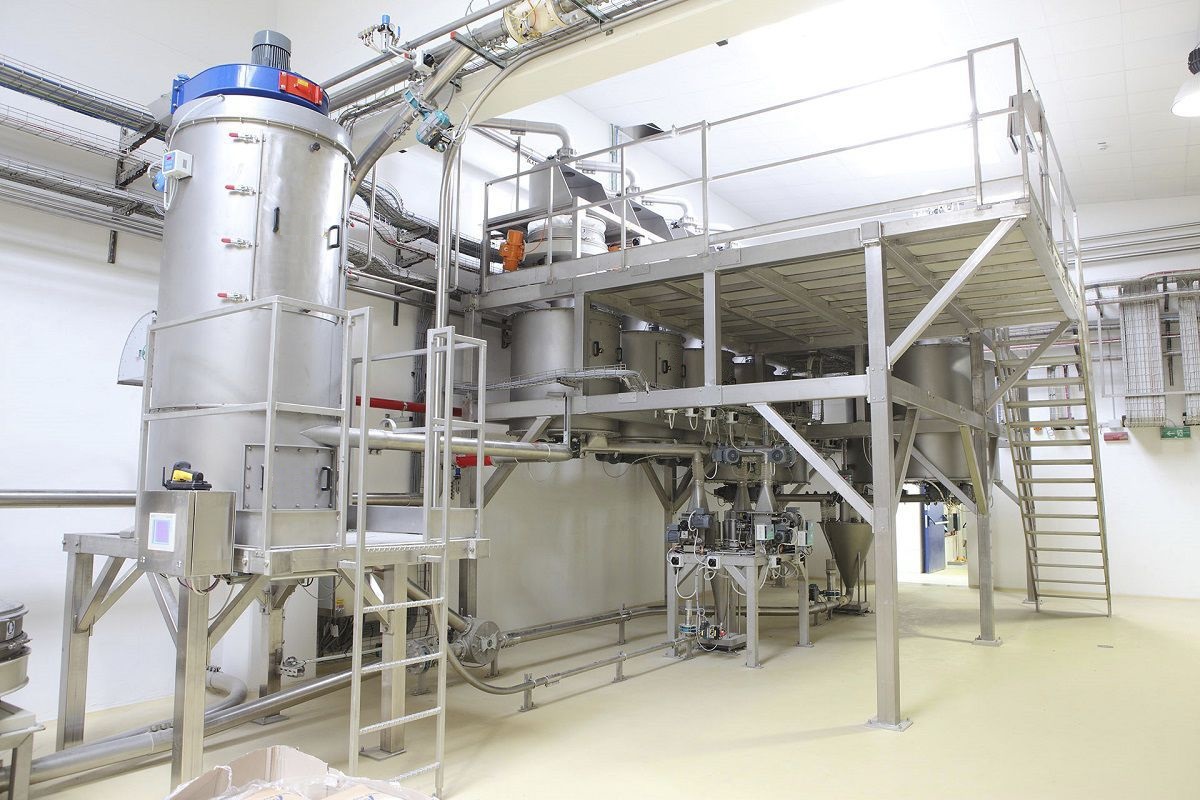
The automatic reaction vessel Weighing system performs the weighing and ratioing of the main ingredients and various additives. After the additives are mixed and blended, they are grouped and classified for further addition. It realizes the metering of the filling process for the weighing reaction vessel. The configuration software "Configurator" from the leading group in the domestic industrial control field is adopted, which has the advantages of good openness, facilitating user maintenance and secondary development. All process control data and equipment operation status of the system can be centrally managed, recorded in real time, and printed and accessed at any time. Communication with the central control room is achieved through the MODBUS bus, allowing for independent control or PLC online control. The position signals of each valve and the discharging device are detected using weighing sensors, featuring no contact, anti-interference, dust resistance, and moisture resistance. The position of the silo is detected using a weight hammer type level gauge, enabling continuous position detection. The weighing system mainly consists of a touch screen, with PLC serving as an auxiliary control system. The human-machine interface displays the ratio parameters (formula) and monitors the real-time data. Under the automatic control mode, by clicking the "start" button for automatic ingredient addition in the screen or the "start" button on the control cabinet, the touch screen will open the material valve of the Electronic scale according to the preset formula. If the system detects that the ingredient valve of a certain electronic scale is not closed, an alarm will occur and the system will enter a suspended state. Each electronic scale has an advance quantity set according to the speed of material weighing. When the weight reaches the set value, the advance quantity will be subtracted, and the weighing instrument will close the feeding valve. The advance quantity can be manually corrected or automatically corrected, ensuring that the control instrument controls the weighing system to achieve the set target value for each ingredient addition.
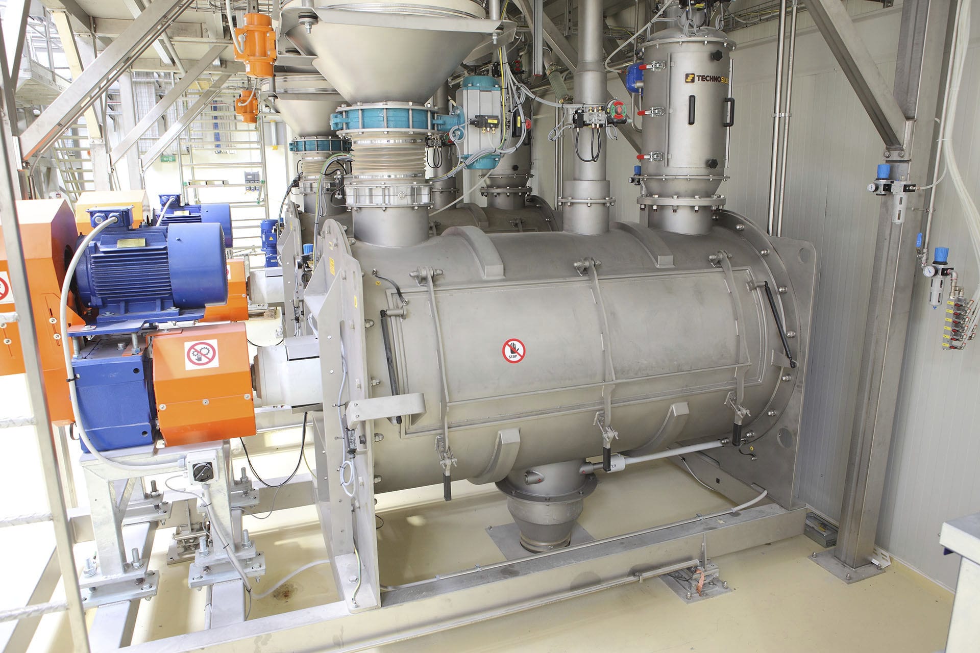
The reaction vessel weighing system mainly includes the upper computer, weighing controller, various component reaction vessels, variable frequency screw ingredient mixer and control valve group, weighing system and mixer, etc. The controller acts as the master station and communicates with the upper computer and the weighing system through the MODBUS bus. The PLC regulation system used in the weighing system is based on the controlled object of the ingredient mixer, real-time quality feedback (feedback information from the weighing system) and the PLC controller. The system aims to output the target quality of each component, and the actual quality output by the ingredient mixer is the input quality. The error generated between the two is used to regulate the real-time quality of the ingredients for the control system. The multi-stage variable speed ingredient mixer controls the speed of the ingredient mixer and the corresponding time according to the input and feedback deviation, based on the set ingredient parameters (ingredient mixer speed and corresponding time), thereby controlling the output quality of the ingredient mixer. If the parameters are set appropriately, within the set error range. Once the formula changes or the Feeding machine speed changes, the ingredient parameters need to be adjusted significantly. At this time, due to the uncertain initial parameters of the controlled object (or unknown beforehand), the on-site operators usually can only give approximate ingredient parameters, and the initial parameters of the controller cannot be adjusted well. There is a large error between the output of the controlled object and the target output. When the PLC error is introduced into the PLC control system, after the PLC control law operation, the new control action is generated to control the controlled object. Thus, the output of the controlled object asymptotically follows the target output until within the set error range.
The weighing system is written in VB and can download formulas, set ingredient parameters, etc. through the upper computer. The ingredient controller automatically selects the silo according to the formula requirements, starts the variable frequency screw ingredient mixer and control valves under the control of the corresponding reaction vessel, and reads the material quality from the weighing system for detection and judgment. According to the PLC multi-stage variable speed control algorithm, the speed of the ingredient mixer is controlled to achieve the control of the discharging speed. If the final weighing quality is within the allowable error range, the discharging of this component is completed. If the allowable error is exceeded, an out-of-tolerance alarm will be issued. After the operator handles it, the component is placed in the mixer, and then the next component's ingredient addition begins. Before the next batch of ingredient addition, the system will automatically adjust the weighing parameters to gradually bring the ingredient quality within the allowable error range. After all components have been weighed, the mixer begins to mix according to the formula settings.
The weighing system adopts a multi-level variable-speed batching control strategy to achieve the best batching accuracy and speed. The batching process is divided into three stages: high-speed batching, slow-speed batching, and pulse batching. The multi-level variable-speed batching control curve includes the speed curve of the batching machine and the material mass curve on the weighing system. Parameters such as the switching point between fast and slow speeds, the pre-cut point, the time for switching between fast and slow speeds, the speed of the batching machine, and the maximum number of batching pulses can all be set through the upper computer. When starting the batching, the speed of the batching machine is set to high speed. At this time, the material mass on the weighing system increases rapidly. When the material mass reaches the pre-cut point, the batching machine completes the switching between fast and slow speeds within the pre-cutting time. The target time for slow batching is set as the weight of the batch. When the material mass reaches the pre-cutting point, the batching machine stops discharging. Due to the existence of "air discharge", the material mass on the weighing system still increases during the stable time. When the stable time ends, the weighing system should have three possible results: first, it is exactly within the allowable error range, indicating that the set batching parameters are good and the current parameters should be saved; second, the deviation is too large and exceeds the positive deviation of the target weight, and the Batching system cannot adjust the result, and the batching parameters need to be adjusted; third, the deviation is too large and is below the negative deviation of the target weight. The batching system enters the pulse batching stage and controls the screw to move point-by-point until the batching quality is within the batching error allowable range.
The batching parameter setting interface is mainly used for setting the pre-cutting, tolerance, and batching parameters. The pre-cutting part is used to set the quality of the fast/slow switching point, the pre-cutting point quality, and the maximum correction quality for pre-cutting. It is important to note that the maximum correction quality value is this parameter, which is used to set the adjustment range to prevent excessive adjustment during optimization. This parameter will be used in the subsequent correction formula. The tolerance setting part is used to set the positive and negative error range of the mass (i.e., the dead zone range), which can be divided into absolute mass error and relative mass error. In actual use, the smaller of the two values is taken and used in the calculation. Additionally, this part is also used to set the system's automatic reset error range, which is also divided into absolute error and relative error. When the difference between the actual batching quality and the target quality exceeds the dead zone within the automatic reset error range, the system automatically receives this quality and completes the batching; if the difference exceeds the dead zone range outside the automatic reset error range, the system outputs an alarm, and the operator confirms to complete the batching. When the next batch of batching is performed, the parameters are adjusted to finally make the actual quality reach the set dead zone range. The batching parameter part is used to set the fast batching speed, slow batching speed, pulse time, etc.
The weighing system parameter setting interface is mainly used for setting the batching monitoring parameters, liquid addition parameters, batching parameters, and correction parameters. The batching monitoring parameters part is mainly used to set parameters such as delay monitoring time, monitoring cycle time, and stable time. The delay monitoring time refers to the system's automatic monitoring of whether the discharging quality of the batching machine reaches the minimum discharging quality set for fast/slow feeding monitoring within this time period. If it does not reach, an alarm is output indicating a shortage of material. The stable time is used for delay monitoring of the actual batching quality to improve system stability. The liquid addition parameters part is used to set the actual calibrated unit pulse liquid mass. The system will calculate the added liquid mass based on the collected pulse quantity. The batching parameter setting part is used to set parameters such as the monitoring cycle for emptying, the quality of emptying monitoring, the maximum emptying time, the emptying quality of the electronic scale, and the delay closing time for the electronic scale to empty. The emptying monitoring cycle refers to setting a time period during which if the discharging quality of the electronic scale is less than the set monitoring emptying quality, an alarm is output indicating an electronic scale discharging fault. When the electronic scale shows a quality less than the set emptying quality of the electronic scale, the system task is to empty the electronic scale discharging valve after the delay setting time.


