


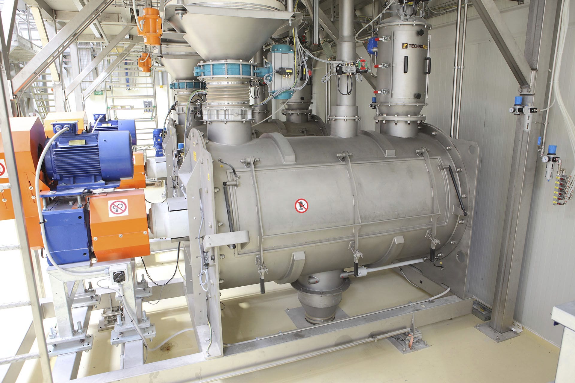


The weight of the materials inside the screw hopper scale is converted into an electrical signal by the weighing module and transmitted to the weighing instrument. The weighing instrument compares and distinguishes the calculated material weight with the preset upper and lower limit values of weight, and controls the feeding gate through PLC to intermittently feed materials into the weighing hopper. At the same time, the weighing instrument compares the actual feeding rate (discharge flow rate) calculated by itself with the preset feeding rate, and uses PID regulation to control the discharge device, so that the actual feeding rate accurately follows the set value. When the feeding gate is opened to feed materials into the weighing hopper, the control signal locks the feeding rate and performs volumetric discharge. The weighing instrument displays the actual feeding rate and the cumulative weight of the discharged materials.

 020-34563445
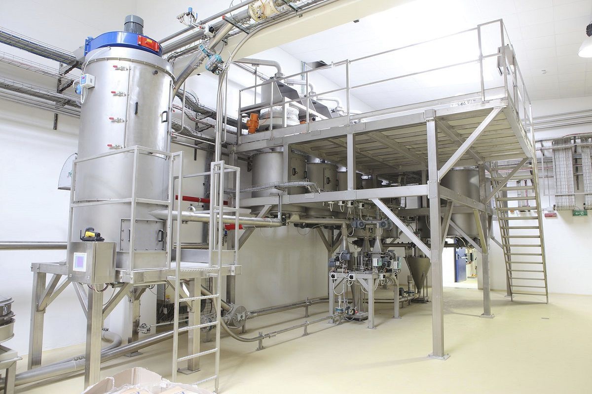
The screw bin scale is installed on the Electronic scale (or multiple weighing module frame installation structure). When the Feeding machine is running, the motor drives the feeding screw or pump to move. At this time, the materials in the bin scale flow out. The actual feeding amount can be obtained by measuring the decrease in weight within a unit time. The error value is compared with the set feeding amount, and then the feeding motor speed is adjusted through the PID closed-loop control algorithm to achieve precise feeding requirements.
The bin scale continuously weighs the entire feeding mechanism, which is equivalent to a static scale. At the same time, the discharge flow of the variable frequency speed regulation mechanism is controlled. The target amount of material weight reduction per unit time corresponds to the feeding flow of the bin scale. The bin scale controller compares the target amount with the preset feeding flow and automatically corrects it by adjusting the speed of the feeding machine. Therefore, an accurate feeding flow can be maintained. When the material weight in the bin scale is lower than the preset value, the bin scale control weighing module will lock the feeding machine speed and keep the discharging mechanism discharging in a volumetric manner, while opening the feeding valve to quickly add materials. When the material weight in the bin scale reaches the high preset value, the feeding valve will automatically close. At the same time, the bin scale controller automatically switches the discharging mechanism to the weighing mode for feeding.
The screw conveyor starts, and the materials are continuously and uniformly discharged downward. The material in the weighing bin gradually decreases, and the weighing bin enters the weightless measurement stage. The weight reduction of the materials within a unit time is calculated to obtain the precise flow of the materials. The weight of the materials in the weighing bin is converted into an electrical signal by the weighing module and sent to the weighing instrument. The weighing instrument compares and distinguishes the calculated material weight with the preset upper and lower limit values and controls the feeding gate through PLC. Intermittently, materials are fed into the weighing bin by the feeding machine. At the same time, the weighing instrument compares the actual feeding rate (discharge flow) calculated with the preset feeding rate and uses PID regulation to control the discharge device to make the actual feeding rate accurately track the set value. When the feeding gate is opened to feed materials into the weighing bin, the control signal locks the feeding rate and performs volumetric discharging. The weighing instrument displays the actual feeding rate and the cumulative weight of the discharged materials.
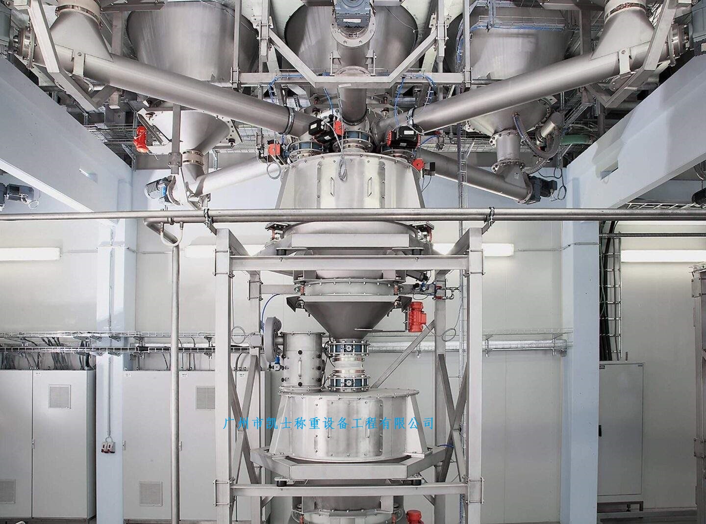
The bin scale has three material levels distributed from low to high, namely the analog material level, the middle material level, and the high material level. Now, except for the 222W analog material level which is an insert-type material level, the material levels on other scales are top-hung lock-type material levels. When the bin scale is performing weighing operations, the upstream process first adds materials to the bin scale, and when there is a certain accumulation of materials in the bin scale, the material surface reaches the analog material level position, and the feeding door of the bin scale will open, and feeding begins for measurement. If the flow rate of the upstream process is greater than the weighing efficiency of the scale, the materials in the bin scale will gradually increase, and when it accumulates to the middle material level position, the outflow pneumatic valve at the starting point of the upstream process will automatically close; when it reaches the high material level position, the upstream process of the bin scale will immediately stop. During normal operation of the bin scale, to ensure the stability of the material feeding weighing of the scale, when the scale reaches the natural non-discharging state, there will be a certain amount of material left below the analog material level.
During the continuous operation of the bin scale, this part of the material is constantly updated and replaced by the materials supplied by the upstream process. However, through the analysis of the discharging situation of the bin scale's upper hopper during its working state, due to the conical design of the upper hopper, the cross-sectional area of the conical discharge opening and the cross-sectional area of the rectangular cross-section of the upper hopper are significantly different, resulting in a "core flow" phenomenon when the material, a fluid, discharges in the conical hopper. That is, starting from the center position of the upper surface, the material at the center is exhausted first, and then the material on the outer circle of the inner wall of the upper hopper is discharged. During the scale's operation, the upstream process supplies materials continuously to the center position of the upper surface, only the center material is constantly replaced and updated, while the material on the outer circle near the inner wall of the upper hopper remains basically unchanged. When the material flow passes through the hemispherical drop-breaking device above the hopper and enters the scale hopper, the dust and light-weight impurities splashed off will fall back onto the surface of the accumulated material and the inner wall of the hopper. Since the material on the outer ring of the scale is basically stationary during operation, and the slope of the inclined part of the conical hopper is relatively gentle, when the dust on the outer ring and the inner wall gradually accumulates to a certain amount, finally, by simulating the discharge of materials and cleaning the scale, these accumulated dust impurities will be concentratedly discharged. The dust accumulated on the hopper of the material flow meter is mainly generated by the dust splashed off when the material flow enters the hopper of the material flow meter and then falls back. To reduce the fall of the splashed dust, it is advisable to appropriately increase the dust collection points of the dust collector on the hopper of the scale. This can make most of the dust splashed off on the hopper of the scale be sucked into the dust collector by the suction points and be uniformly returned to the downstream process of the scale through the dust collection system. This can also to some extent avoid the accumulation of dust in the hopper of the material flow meter and finally concentrate and discharge it.


