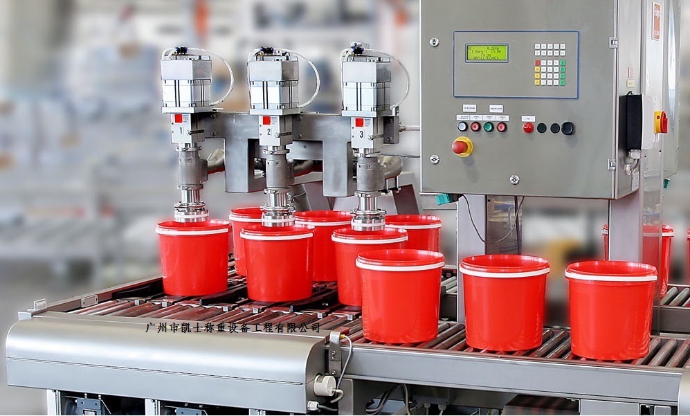


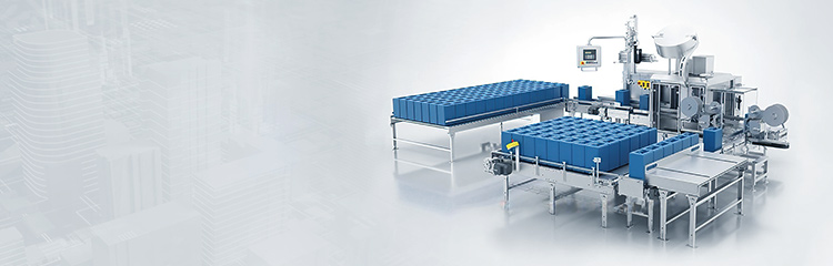

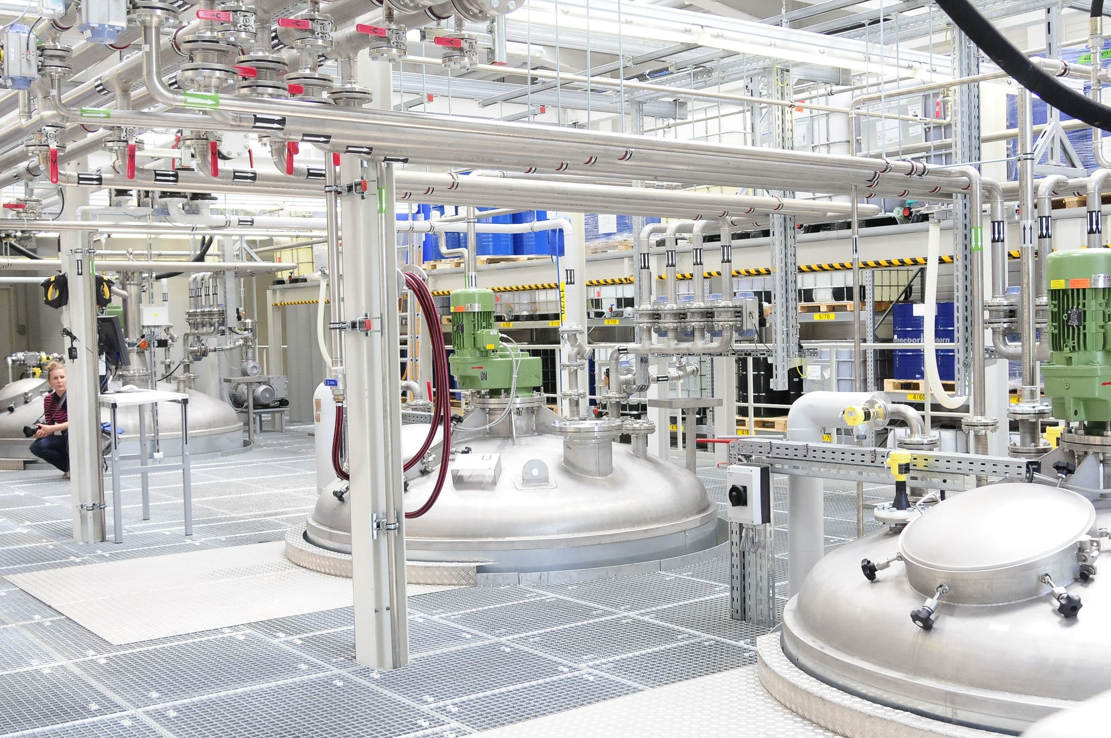


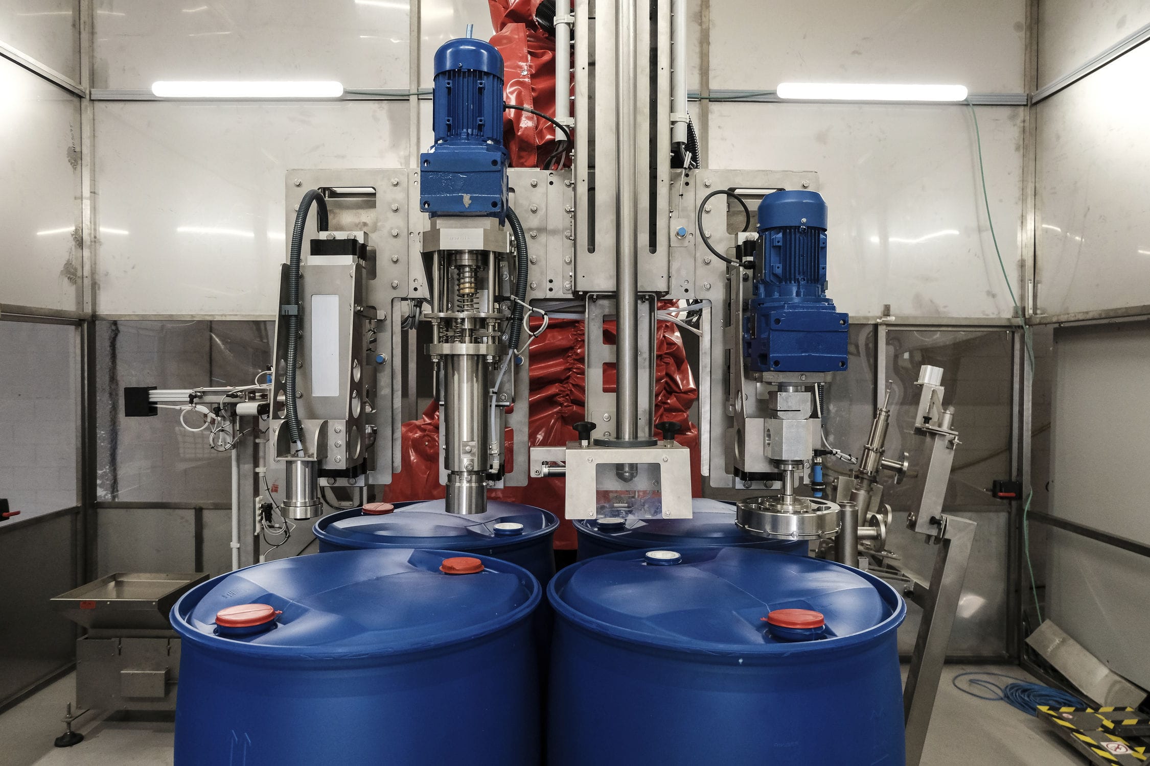
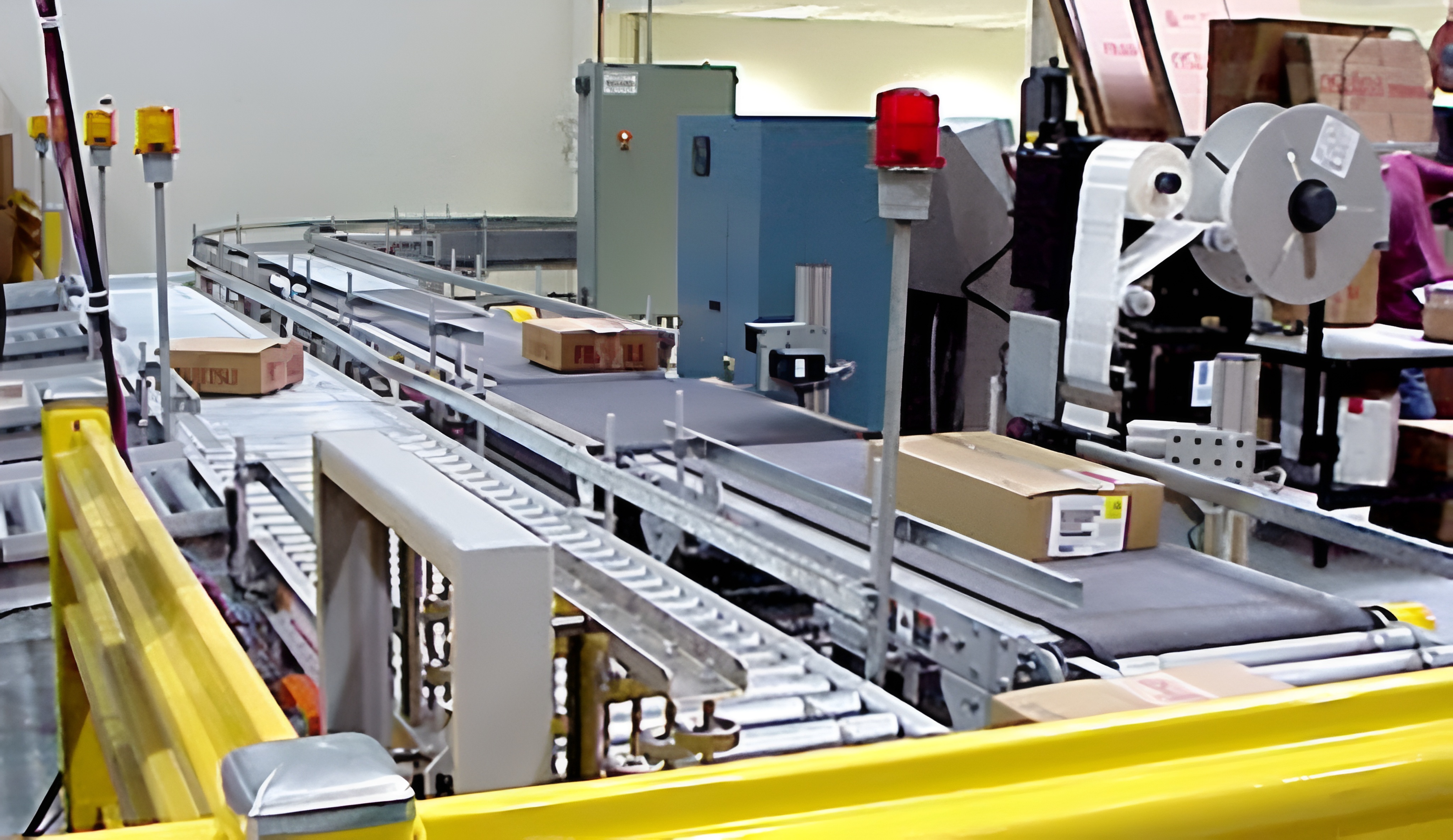


Lubricating oil filling machine set control plastic drum disinfection, bottle delivery, quantitative filling, cap feed and cap rolling and other functions in one, controlled by the frequency converter continuous rotation operation of the large plate using the barrel positioning technology to achieve the feed of the control drum, the whole circumference of the rotating plate is evenly divided into multiple groups, each group has multiple barrels to be filled at the same time, when the filling signal arrives, A plurality of filling needles are controlled by a CAM mechanism operating in coordination with the rotary plate to drop to a certain depth in several drums, and at the same time run synchronously with the rotary plate and fill.


 020-34563445
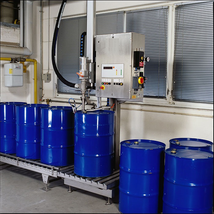
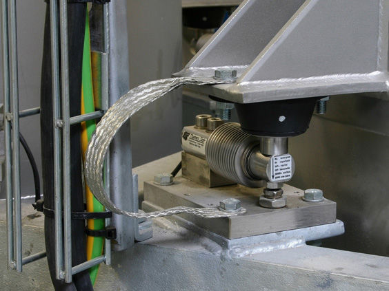
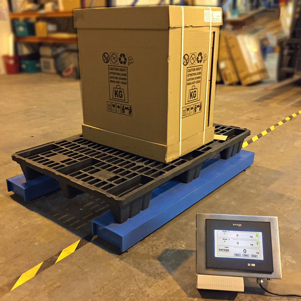
The automatic Filling machine is a high-precision, high-tech product that is set for measurement by an Electronic scale platform under the control of a microcomputer program It is a new type of machine that integrates machinery, electricity, and instrumentation. It has changed the traditional flow meter based filling quantitative accuracy and the inability to measure viscous liquids, and is an ideal filling equipment that integrates weighing and filling after the elimination of lever scales in civilized production and national regulations. During filling, the tare weight is automatically removed. When the material is injected into the container, it is quickly filled in large quantities and then slowly measured in small doses. The operator only needs to place the container on the platform, align the barrel mouth with the filling nozzle, and the program starts. The filling nozzle descends, and the filling valve is opened for feeding. When the set amount is reached, the filling stops automatically and the filling nozzle rises to complete the filling process. The main function of a weighing and filling machine is to fill liquid media into packaging containers to achieve functions such as filling, sealing, weighing, and stacking. The Filling system adopts sequential control, motion control, communication, and data management microprocessor technology and communication technology to filter, judge, and store input signals, and transmit output signals to the execution mechanism of the filling system to complete filling commands. It also controls the real-time position of the barrels in the online container, uses pressure control to pre press the filling barrels, adjusts the speed of the conveyor chain, and coordinates the feed speed of each dragging point of the entire production line when the containers on the conveyor chain are blocked. The coordination signal is dragged to other conveyor chains in the production line, and the control system also performs real-time detection and control of empty/full barrels, stacking, capping, opening/closing filling valves, etc. The PLC signal is used to drive the motor and other transmission mechanisms to move the robotic arm. At the same time, the encoder built-in to the motor feeds back the number of pulses to the driver to compare the two types of pulses and determine the deviation. The correction signal obtained by calculating according to a certain control law is used as the given value of the speed controller in the servo drive. After current adjustment and power amplification, the grasping robotic arm moves in the direction of eliminating the deviation, thereby achieving the stacking positioning of the robotic arm.
The automatic filling machine is equipped with a base, a support box, and a weighing scale. The support box is fixedly set on the top of the base, and there is an opening on the front side of the support box. The top of the base is provided with a groove for placing a double-layer weighing scale, and an electronic weighing scale is fixedly set in the groove. The top of the explosion-proof weighing scale is equipped with a filling gun. The support box is equipped with a lifting structure, and the lifting structure is equipped with an adjusting structure; The lifting structure includes a first protective box, a first cylinder, a screw, two limit rods, and a support plate; The first protective box is fixedly installed at the top outside the support box, and the first cylinder is fixedly installed inside the first protective box. The bottom end of the screw is movable and embedded in the bottom of the support box, and the top end of the screw is movable and penetrates through the top of the support box. The top end of the screw is fixedly connected to the driving end of the first cylinder. Two limit rods are fixedly installed inside the support box, and the two limit rods are located on the left and right sides of the screw. The support plate is of an "I" - shaped structure, and the support plate is movable and penetrates the front opening of the support box. The rear side of the support plate is fitted with the screw and two limit rods, and the support plate is connected to the screw screw. The adjustment structure includes a fixed box, an adjustment box, a second protective box, a second cylinder, a screw, two sliding rails, a moving seat, two connecting rods, an adjustment seat, an oil pipeline, an electromagnetic valve, and an oil discharge pipe. The fixed box is fixedly set on the top of the support plate, and the fixed box is located on the front side outside the support box. The adjustment box is fixedly set on one side outside the fixed box. The second protective box is fixedly set on the side outside the adjustment box away from the fixed box. The second cylinder is fixedly set inside the second protective box. One end of the screw is flexibly embedded on the side of the fixed box near the adjustment box, and the other end of the screw is flexibly penetrated on the side of the adjustment box near the second protective box. The other end of the screw is fixedly connected to the driving end of the second cylinder. The two sliding rails are respectively Fixed at the top and bottom of the adjustment box, the movable seats are respectively fitted with screws and two limit rods, The mobile seat is connected to the screw screw spiral, and two connecting rods are movable through the side of the fixed box near the adjustment box. One end of the two connecting rods is fixedly connected to one side of the mobile seat, and the adjustment seat is fixedly connected to the other end of the two connecting rods. The adjustment seat is located inside the fixed box, and one end of the oil pipeline is fixedly placed at the top of the fixed box, and the oil pipeline is connected to the fixed box. An electromagnetic valve is fixedly installed on the oil pipeline, and the oil pipeline runs through the support plate. The oil pipeline is fixedly placed at the bottom of the fixed box, and the oil pipeline is connected to the fixed box. The positions of the oil pipeline and the oil pipeline correspond. There are two fixed seats fixed on the left and right sides of the top of the base. Two cylinders are fixedly connected to the top of the two fixed seats, and two clamping plates are fixedly connected to the driving end of the two cylinders. The two clamping plates are located on both sides of the filling gun. The outer fixing set of the adjustment seat is equipped with a sealing ring, which is tightly adhered to the inner wall of the fixed box. The output end of the material tank weighbridge is electrically connected to the input end of the second cylinder and the input end of the solenoid valve.