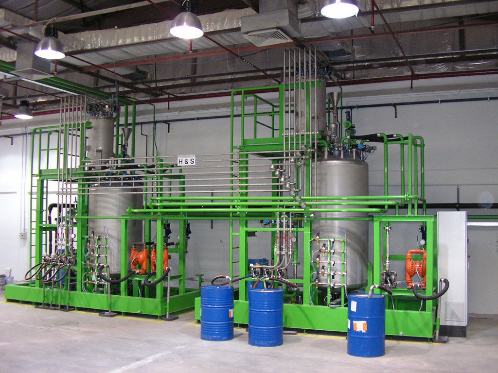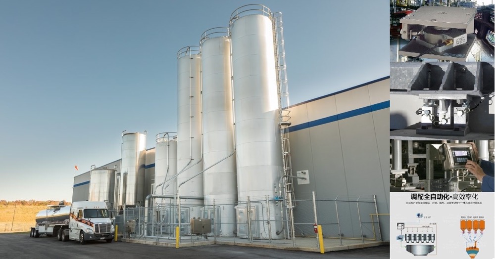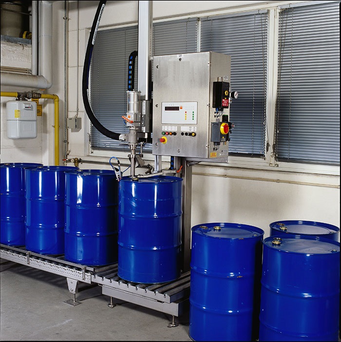


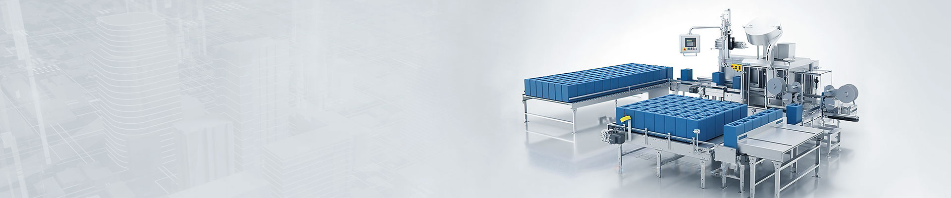



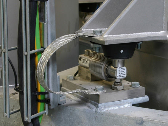
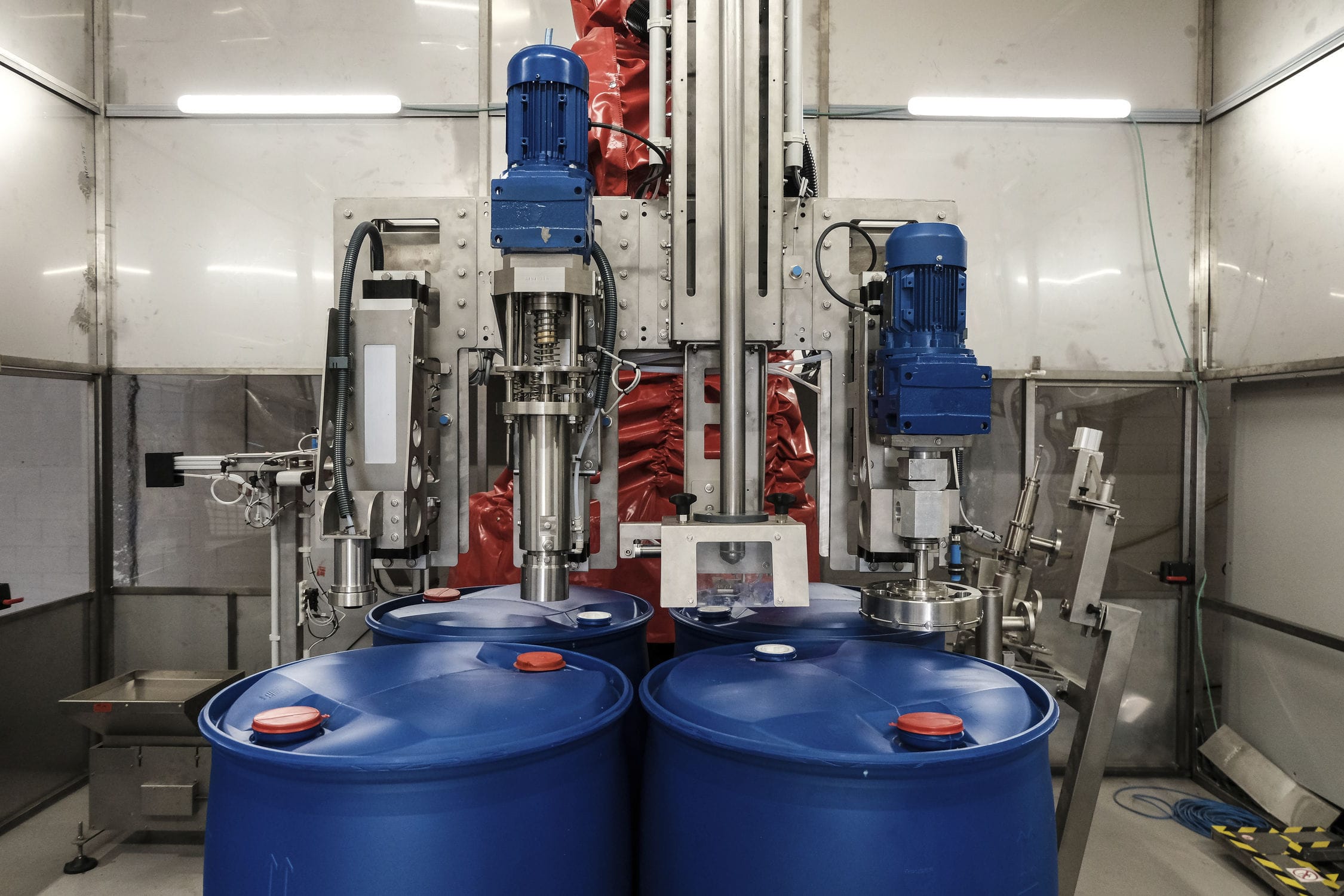
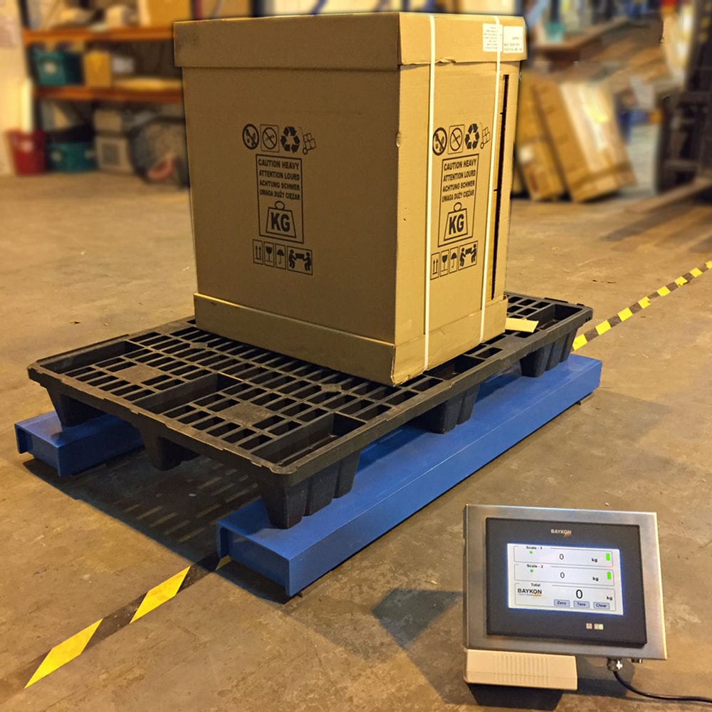


The lubricating oil filling machine mainly adopts the weighing quantitative method, and realizes the quantitative filling of liquid by collecting the data of the weighing module. The signal acquisition circuit is mainly responsible for filling the corresponding instructions, completing the acquisition of the target value in the filling, and passing the pressure value to the next set in the form of A signal A/D conversion circuit is mainly responsible for converting the signal transmitted from the upper level into a signal that can be effectively processed by the computer.


 020-34563445
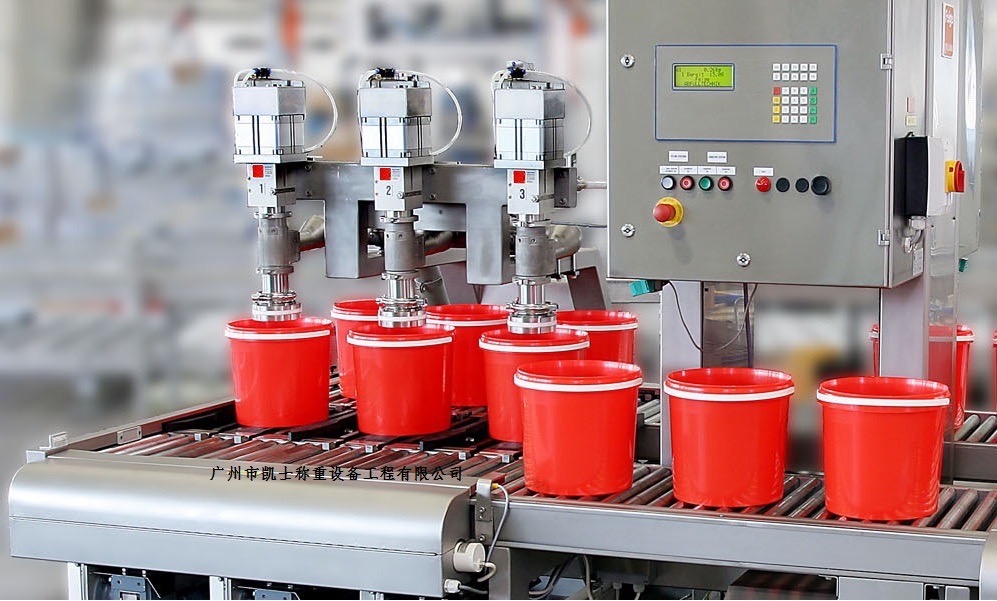
The automatic Filling machine adopts a two-step filling process of coarse and fine filling to ensure filling speed and accuracy. During filling, the submersible bucket is filled into the mouth. After filling, the receiving tray extends to prevent liquid contamination of the packaging and conveyor line. Adopting touch screen human-machine dialogue, automatic diagnostic function, parameter setting, cumulative shift production, work status display, etc., it can automatically remove tare weight, accumulate bucket number, weight, display filling volume, zero point automatic tracking, drop automatic correction, over/under quantity, abnormal operation alarm function. The bottom is equipped with a material receiving tray and a discharge pipe valve, which can store materials for easy discharge. The automatic filling machine mainly uses the weighing and quantitative method to achieve quantitative filling of liquids by collecting data from the measuring module. The filling volume needs to be measured and displayed in real time. The Filling system adopts a weighing module and weighing instrument, with a range of 0-40kg and an output of standard voltage signal 0-10V. The measurement of canned quality is achieved through the analog input channel of EM235, with the port of EM235 set to 0.0010. In order to ensure the filling accuracy, the system has added an electromagnetic valve at the front end of the pump to ensure that the liquid flow can be immediately connected and cut off when starting/stopping. The pump selection parameters are 12VDC flow rate of 3.1L/min and maximum pressure of 0.48MPa. An intermediate relay is used as a converter to control the electromagnetic valve and pump. The manual/automatic switching is achieved through two selection buttons, and secondly, the start and manual filling are achieved through buttons.
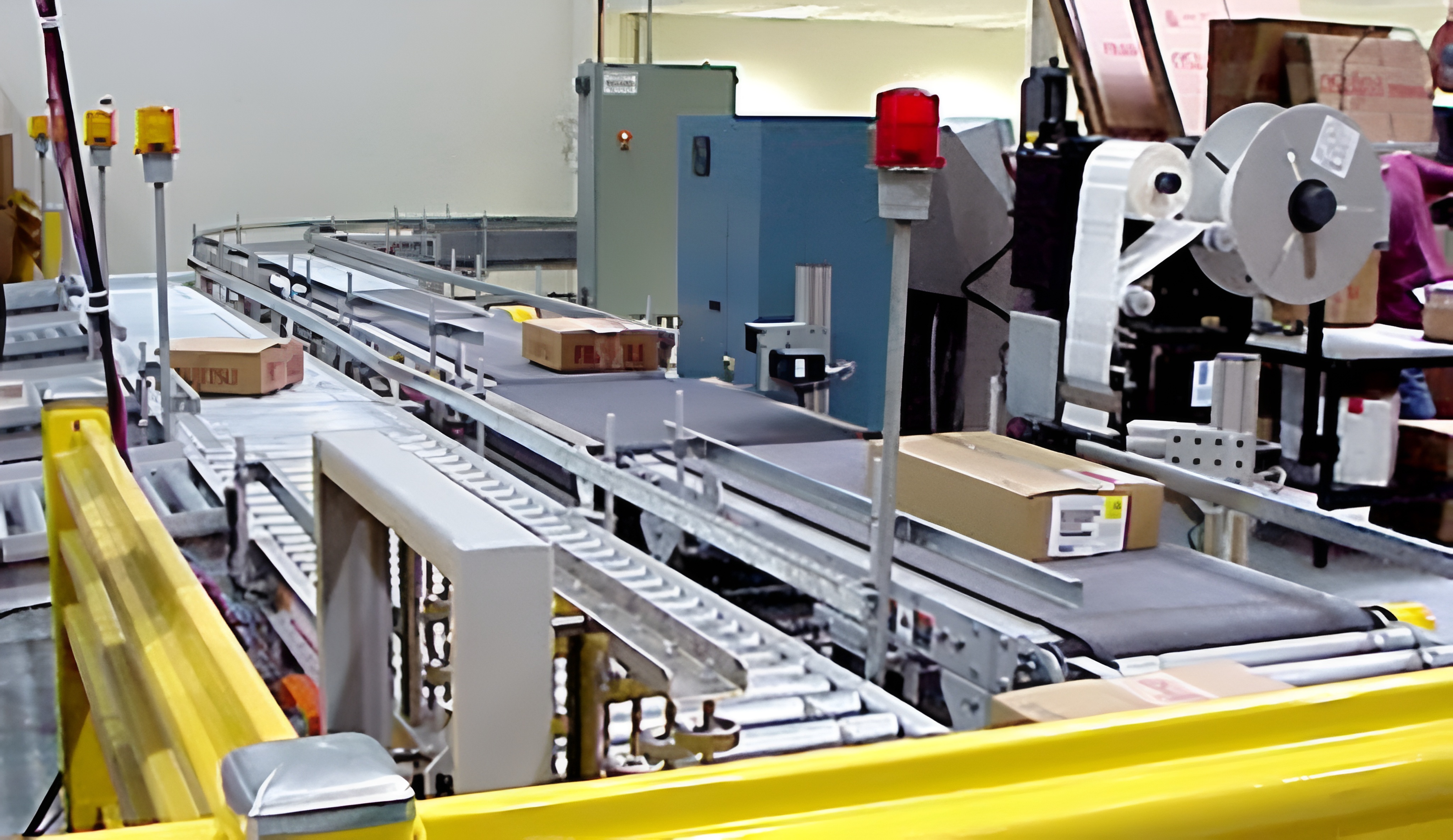
The automatic filling machine has a Y-shaped block welded to the bottom of the side end of the base, and a top mechanism connected below the Y-shaped block. There are several pillars welded to the top surface of the rear end of the base, among which a positioning rod is installed on one side of the rightmost pillar. The top mechanism includes a foot pedal, and the end of the foot pedal is welded with a driving wheel. One side of the driving wheel is engaged with a driven wheel, and the driving wheel and the driven wheel are hinged to the two ends of the block through pins. One side of the driven wheel is welded with a pressure rod, and the end of the pressure rod is hinged with a top rod. The outer side of the top rod is sleeved with a collar, and one side of the collar is welded with a hook spring. One side of the rightmost pillar is opened with a square hole, and one side of the positioning rod is welded with a connecting rod One end of the connecting rod is welded with a concave block, and the inner side of the concave block is equipped with an inclined platform. The outer end of the concave block is symmetrically welded with a reset spring. The top surface of the base is equipped with a roller belt, and one end of the roller belt is equipped with a weighing scale at the bottom. A filling bucket is placed directly above the electronic weighing scale, and there are three pillars. The top of the three pillars are sequentially equipped with a capping machine, an operation panel, and a filling box. The foot pedal and pressure lever form a V-shape when in a stationary state. The other end of the hook spring is welded to the rear side of the base. The top rod is connected to the concave block and slides with the inclined platform. The other end of the reset spring is welded to the rear side of the pillar. The positioning rod has a circular arc structure and is clamped and matched with the side of the filling barrel. By setting a positioning rod on one side of the support column of the capping machine, and pushing the positioning rod out by stepping on the top mechanism, the filling barrel is then pressed together, so that the filling barrel is located directly below the capping machine, which is conducive to accurate capping and improves product quality. Its operation is convenient, saving time and enabling smooth work.