




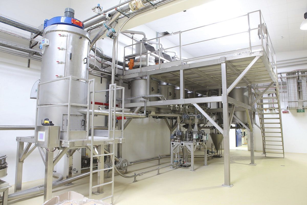
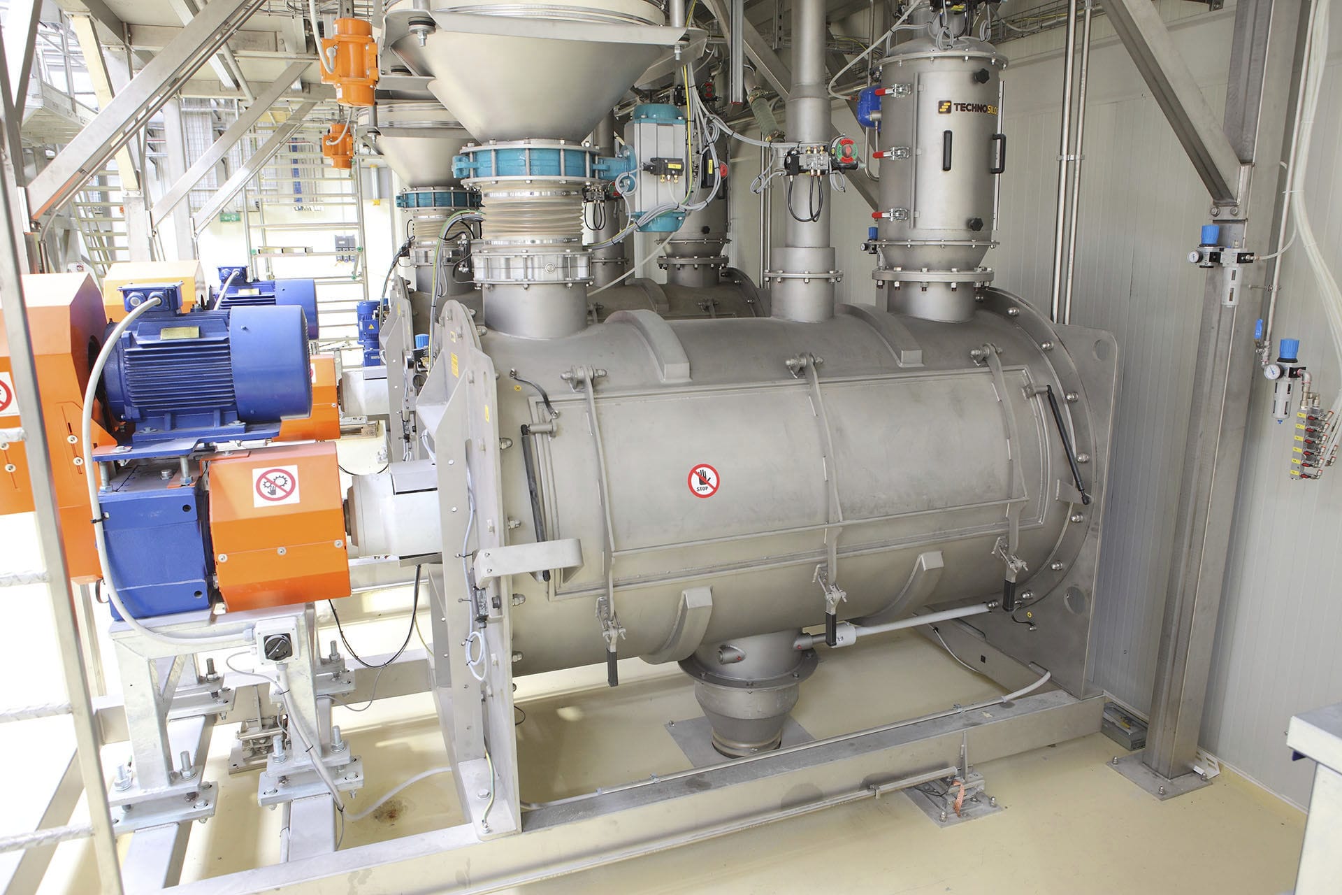
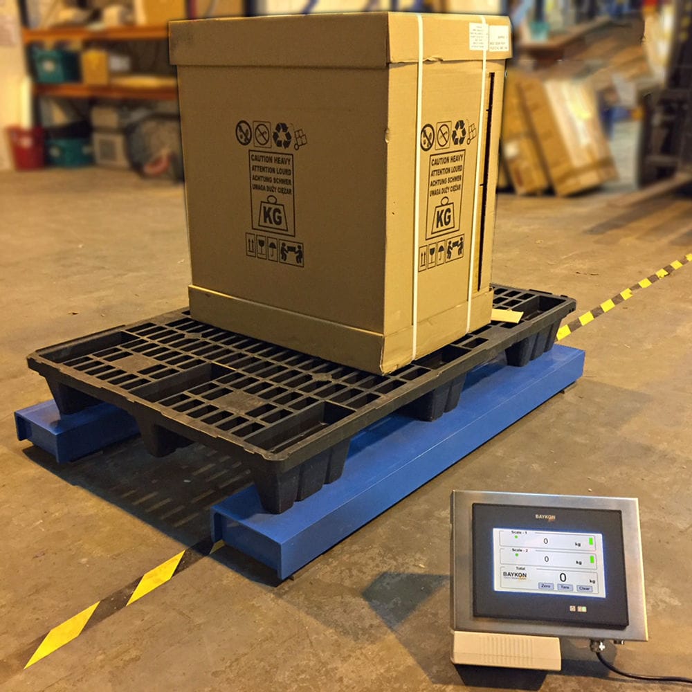


Measurement Explosion-proof filling machine can fully realize the management automation of each phase of business link in oil depot and chemical industry, and carry out automated monitoring for each work link of users, so as to assist the management personnel of users to carry out business processing more efficiently and accurately. Based on the LAN environment, through the unified monitoring interface, it automatically collects the dynamic data of each monitoring environment, and forms various reports (such as oil payment report, unpaid oil report, yearly, monthly, daily report, etc.) and detailed tables based on these monitoring data, which is convenient for business statistics and inquiries.

 020-34563445
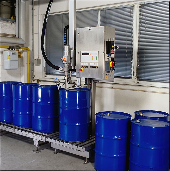
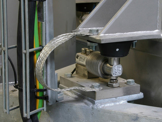
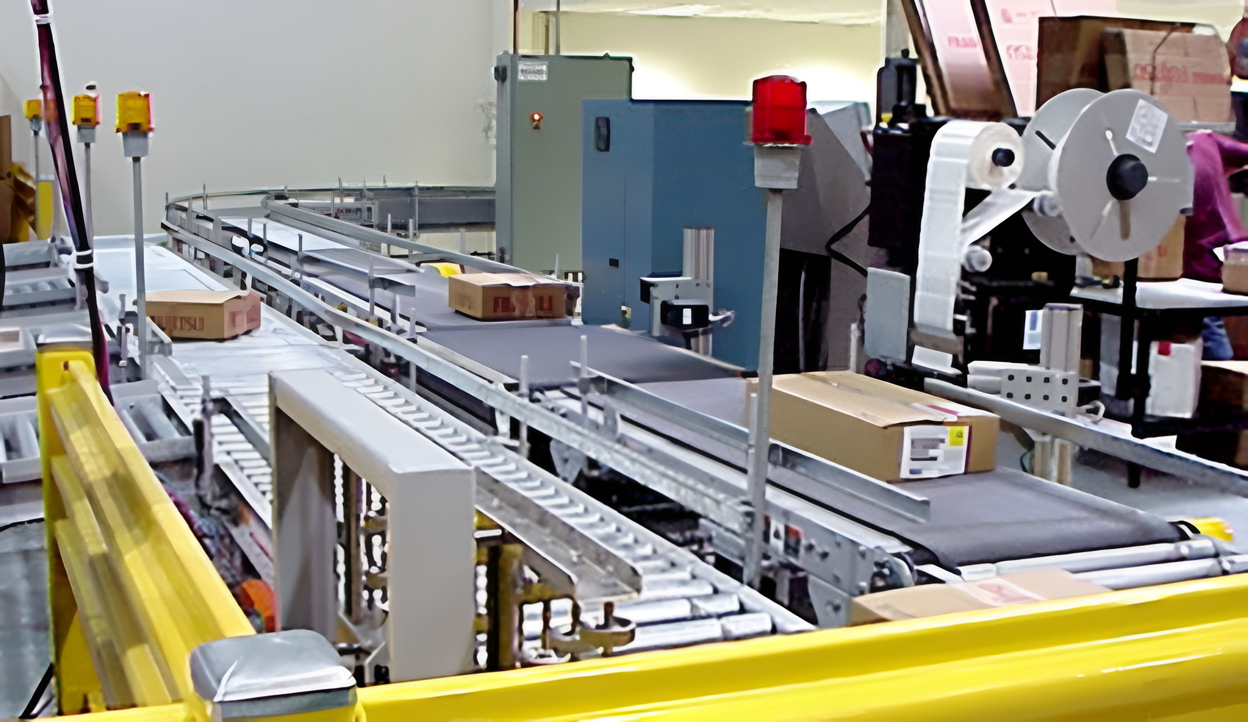
The process flow of online weighing for explosion-proof measuring Filling machine consists of two sets of identical online weighing processes and online quality calibration processes. The two sets of identical online weighing processes are: one is to grab and weigh the iron drum before filling on the conveyor mechanism and put it back, and the other is to grab and weigh the iron drum after filling and put it back. After calculation and analysis by the online Weighing system, the filling error is fed back to the Liquid filling machine for online adjustment of the filling amount. Online weighing process after filling: When the Electronic scale device detects the in place detection signal of the filled iron drum after filling, the conveyor belt conveyor pauses. The main shaft lifting mechanism motor rotates the drum to lower the main shaft into place, and the drum clamp clamps the filled iron drum before lifting it back into place. The conveyor belt conveyor starts. Transfer the filled iron drum to the electronic scale using the drum rotating spindle. Lower the drum rotating spindle to the designated position, release the drum clamp, and once the filled iron drum is in place, perform ingredient testing and output the measured quality input signal of the filled iron drum. Next, clamp the iron bucket with the bucket clamp after filling. The bucket rotating main shaft is lifted into place, rotated, and transferred to the conveyor belt for filling. The automatic filling machine conveyor belt is paused, and the bucket rotating main shaft is lowered into place. Release the bucket clamp after filling the iron bucket, and the bucket rotating main shaft is raised. The conveyor belt is started to complete the ingredient detection action after filling, and this process is repeated.
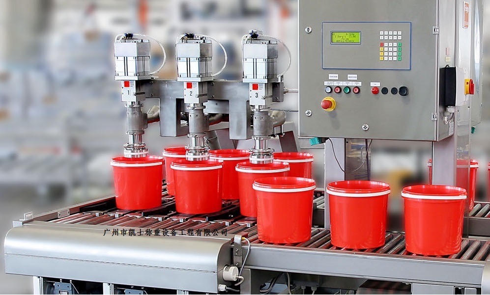
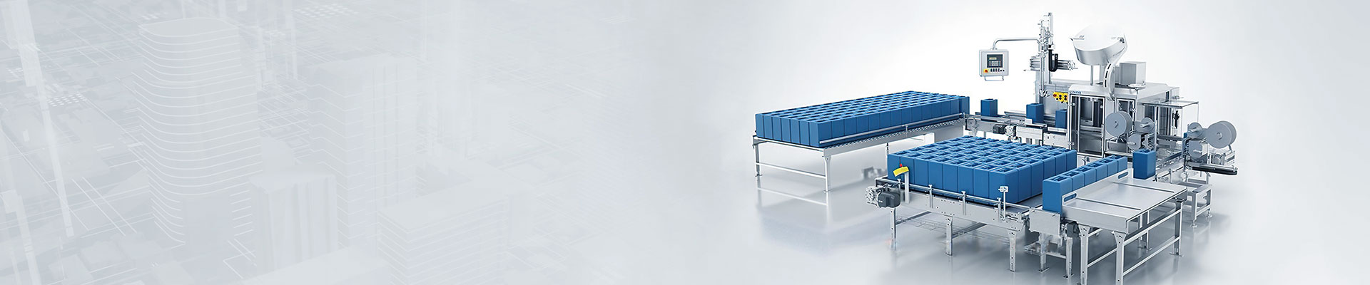
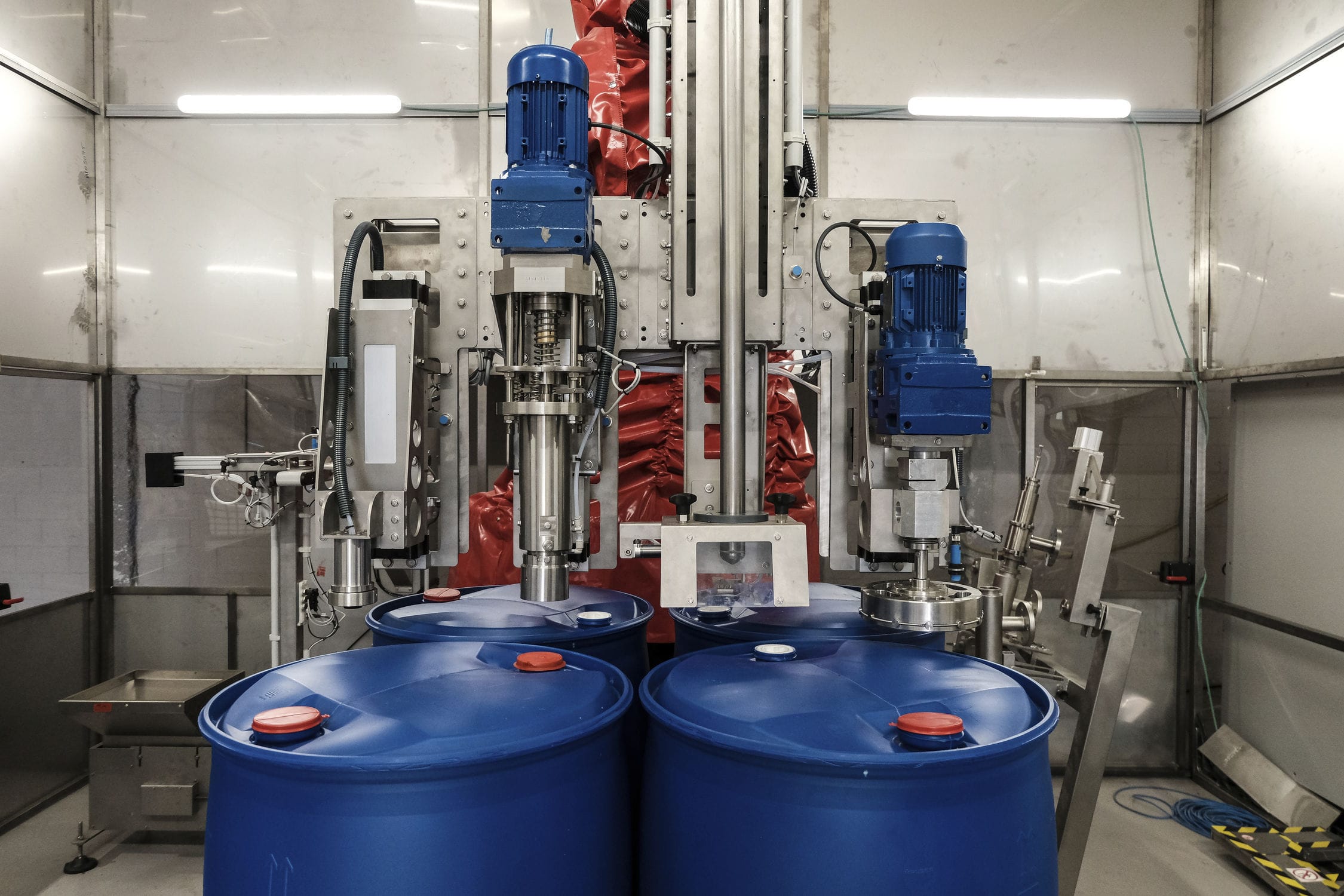
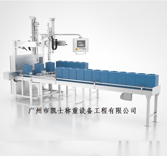
The automatic filling machine adopts a main bracket, a drum conveyor for conveying barrels, filling components, and waterproof weighing scales. There are three baffles on both sides of the drum conveyor, which are evenly spaced and symmetrically arranged relative to the drum conveyor. The baffles are of an I-shaped structure, connected to baffle cylinders, which extend and contract in the direction of the drum conveyor perpendicular to the conveying direction of the drum conveyor. When the piston rod of the baffle cylinder extends, the two symmetrical baffles on both sides of the drum conveyor clamp one barrel, and the L-shaped structure clamps at the two corners in front of the barrel. The baffle cylinder is equipped with a photoelectric sensor for sensing the barrel; There are two sets of filling components. The connection between the two sets of filling components is parallel to the conveying direction of the drum conveyor, and the distance between the two sets of filling components is equal to the distance between the adjacent two baffles on one side of the drum conveyor. The filling components are fixed on the main bracket and located above the drum conveyor. The two sets of filling components correspond to the two buckets at the front end of the running direction that are stuck at the baffles; The filling component includes a filling bracket perpendicular to the horizontal plane, which is equipped with a lifting cylinder on the filling frame. The extension and contraction direction of the lifting cylinder is perpendicular to the horizontal plane and faces the drum conveyor. The side wall of the filling bracket is equipped with a slide perpendicular to the horizontal plane, which is equipped with a sliding block that slides on the slide. The slide is equipped with a filling cylinder, and the extension and contraction direction of the filling cylinder is perpendicular to the horizontal plane and faces the drum conveyor. The filling cylinder is equipped with a hollow tube. The piston rod of the filling cylinder is located inside the hollow tube, and the end of the piston rod is equipped with a plug with a cross-section larger than the internal cross-section of the hollow tube. The plug is located outside the hollow tube, and the side wall of the hollow tube is equipped with a feeding branch pipe. The hollow tube and plug can; There are two sets of material bucket weighing scales below the drum conveyor, and the two sets of double-layer weighing scales correspond to the two buckets at the front end of the running direction that are clamped at the baffle. The top of the stainless steel weighing scale is connected to the top block of the weighing platform through a weighing cylinder. The weighing platform top block includes a support plate connected to the piston rod end of the weighing platform cylinder and two or more weighing blocks arranged at equal intervals on the support plate. The weighing block is a rectangular structure, and the weighing block is parallel to the drum of the drum conveyor and can be inserted between adjacent drums. The filling weighing scale is connected to the weighing frame and the main frame, and the expansion and contraction direction of the weighing cylinder is perpendicular to the horizontal plane. When the weighing cylinder extends, the weighing block is inserted between the drums and the top height of the weighing block is higher than the top height of the drum. The bottom of the filling frame is The liquid bracket is connected to a liquid receiving cylinder, The expansion and contraction direction of the liquid receiving cylinder is parallel to that of the baffle cylinder. The piston rod end of the liquid receiving cylinder is equipped with a liquid receiving disc, which is located directly below the hollow tube when the liquid receiving cylinder extends.
When the quantitative filling machine is working, the baffles on both sides of the drum conveyor are divided into the first baffle, the second baffle, and the third baffle. The first baffle, the second baffle, and the third baffle are arranged in sequence from the outlet end to the inlet end of the drum conveyor. When the first bucket at the front end of the running direction reaches the baffle cylinder of the first baffle, the photoelectric sensor on the baffle cylinder of the first baffle senses the signal, and the first baffles on both sides of the drum conveyor extend. The bucket continues to run forward, and the two corners of the front end of the bucket running direction are stuck by the first baffles on both sides of the drum conveyor; When the second bucket at the front end of the running direction reaches the baffle cylinder of the second baffle, the photoelectric sensor on the baffle cylinder of the second baffle senses the signal. The second baffles on both sides of the drum conveyor extend, and the bucket continues to move forward. The two corners of the bucket at the front end of the running direction are stuck by the second baffles on both sides of the drum conveyor. Then, when the third bucket at the front end of the running direction reaches the baffle cylinder of the third baffle, the photoelectric sensor on the baffle cylinder of the third baffle senses the signal, and the third baffles on both sides of the drum conveyor extend, blocking the subsequent buckets; At this point, the weighing cylinder extends and the weighing block presses against the bottom of the bucket where the first and second baffles are stuck, preventing the bucket from contacting the drum; After the position of the bucket is fixed, the liquid receiving cylinder retracts, which drives the liquid receiving disc to retract. The lifting cylinder extends, causing the slider to move downward along the slide, allowing the hollow tube and plug to extend into the bucket mouth at the main positions of the first and second baffles; Then the filling cylinder extends, the plug is opened, and feeding begins. When the preset weight is filled, the filling scale gives a signal, and the filling cylinder retracts. The plug blocks the hollow tube port, and the lifting cylinder retracts. After the lifting cylinder retracts, the liquid receiving cylinder extends so that the liquid receiving disc is located directly below the hollow tube, preventing the remaining liquid on the plug from contaminating the barrel; After the filling is completed, the weighing cylinder and the first and second baffles retract synchronously, and the subsequent empty barrels continue to enter the filling position, repeating the above operation.
Basic Parameters:
Maximum weighing capacity: 30kg
Minimum sensitivity: 0.1kg
Filling error: ± 0.1-0.2kg
Filling speed: 20L, approximately 1500-1800 barrels per hour
Control mode: 2nd gear control
Filling method: Insertion type, above liquid level
Gun head pipeline: PTFE gun head, valve+PTFE hose
Structural material: SUS304 stainless steel for the host, carbon steel for conveying and stacking with anti-corrosion paint.
Scale platform size: 400 × 800mm (304 stainless steel power raceway)
Empty bucket raceway: 400mm × 2500mm (304 stainless steel power raceway) with an additional 1200mm sloping unpowered drum
Heavy bucket raceway: 400mm × 2500mm (304 stainless steel power raceway, 2 sets)
Bucket sorting device: suitable for 20L buckets, carbon steel anti-corrosion paint structure, 304 stainless steel raceway.
Stacking equipment: translation type, suitable for pallets of 1200 × 1200 × 140mm, including pallet supply, palletizing, and lower pallet conveying.
Pipeline pressure: 0.2-0.6MPa (depending on material properties).
Material interface: 4 DN40 flange joints, available according to user provided interface standards
Air source interface: The user provides a 12mm air hose connector for quick connector connection
Power supply: AC220/50Hz (provided by the user to the machine side)
Gas source used: 0.4-0.8Mpa (provided by the user to one side of the machine)
Operating temperature: -10 ℃ -50 ℃
Basic conditions: A strong horizontal concrete floor with a concrete thickness greater than 10cm.
Optional models: Standard and explosion-proof filling scales