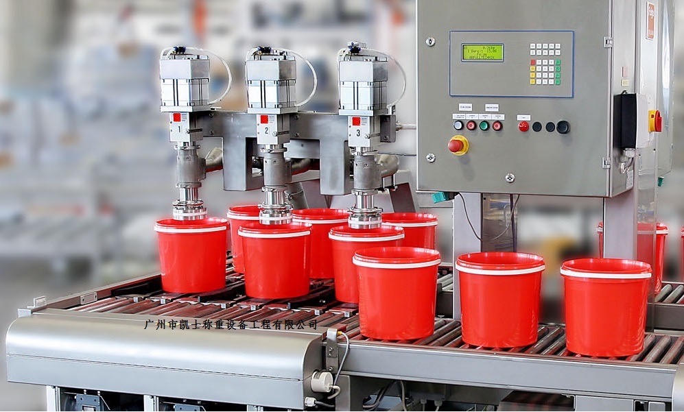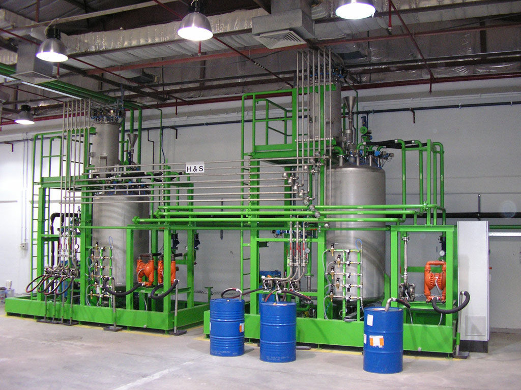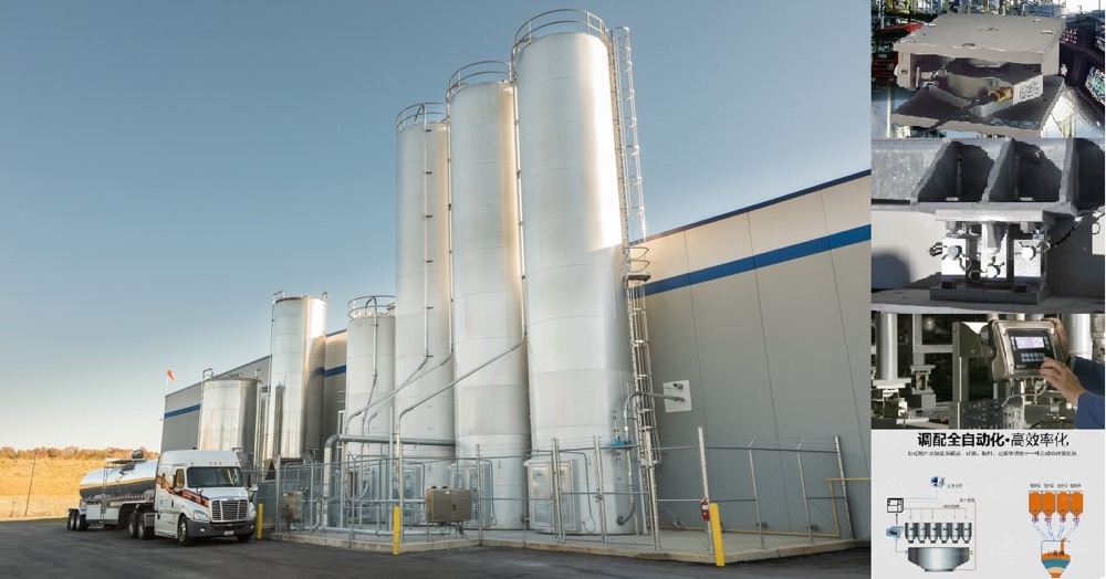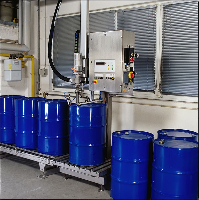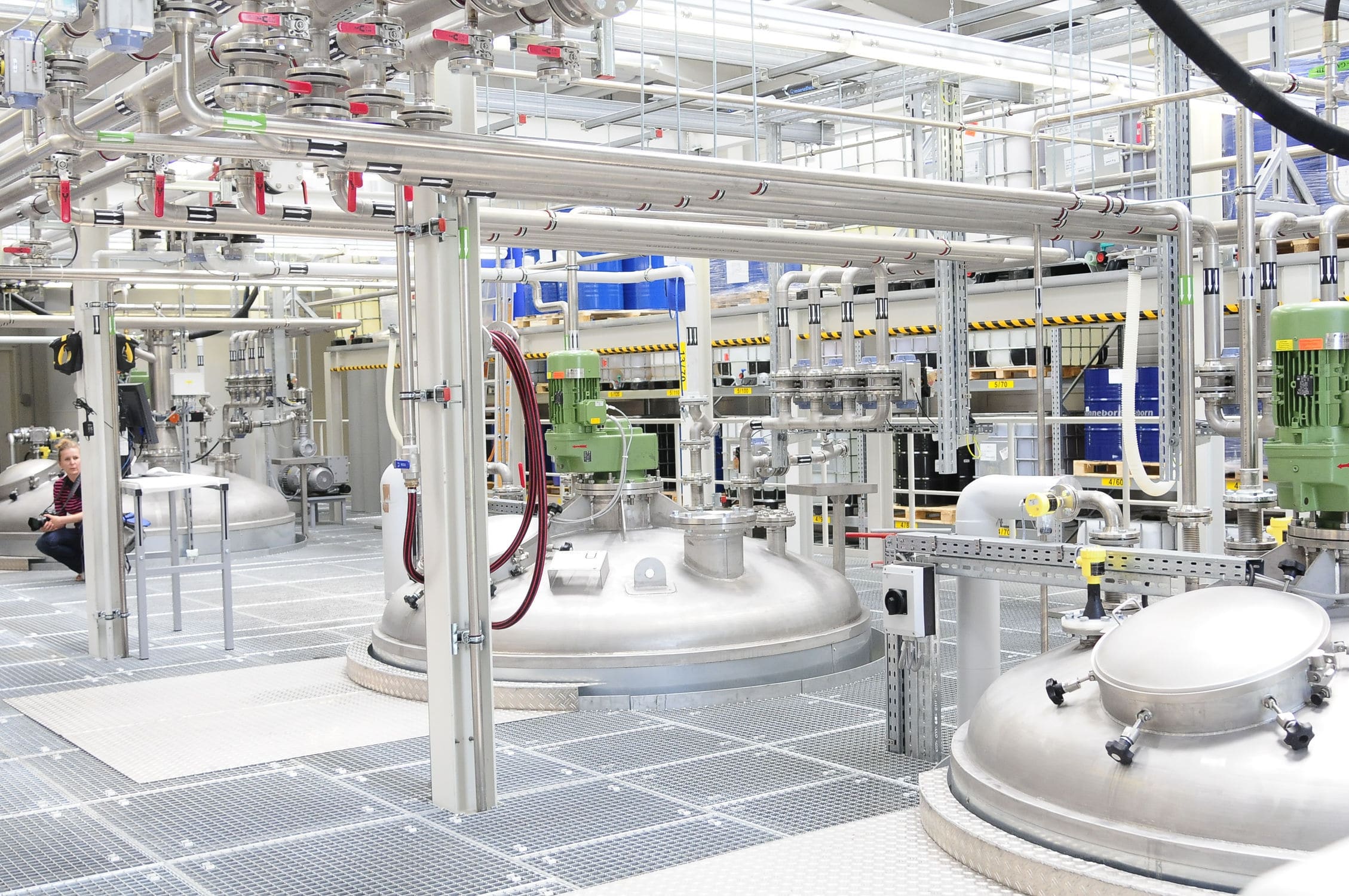


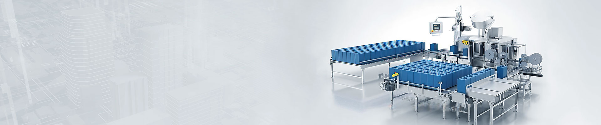


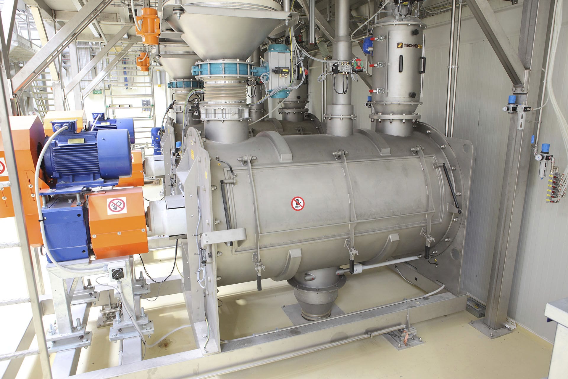
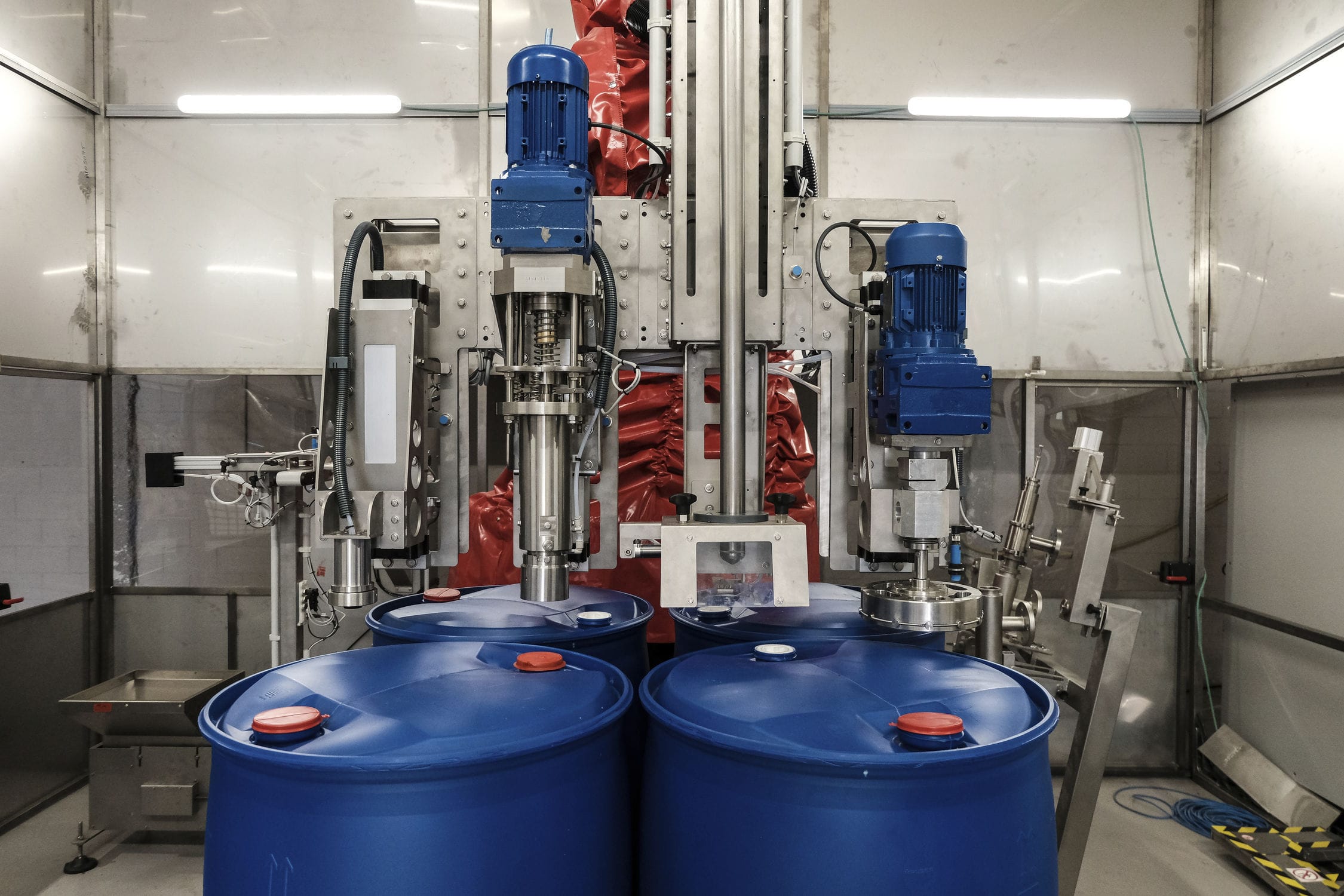
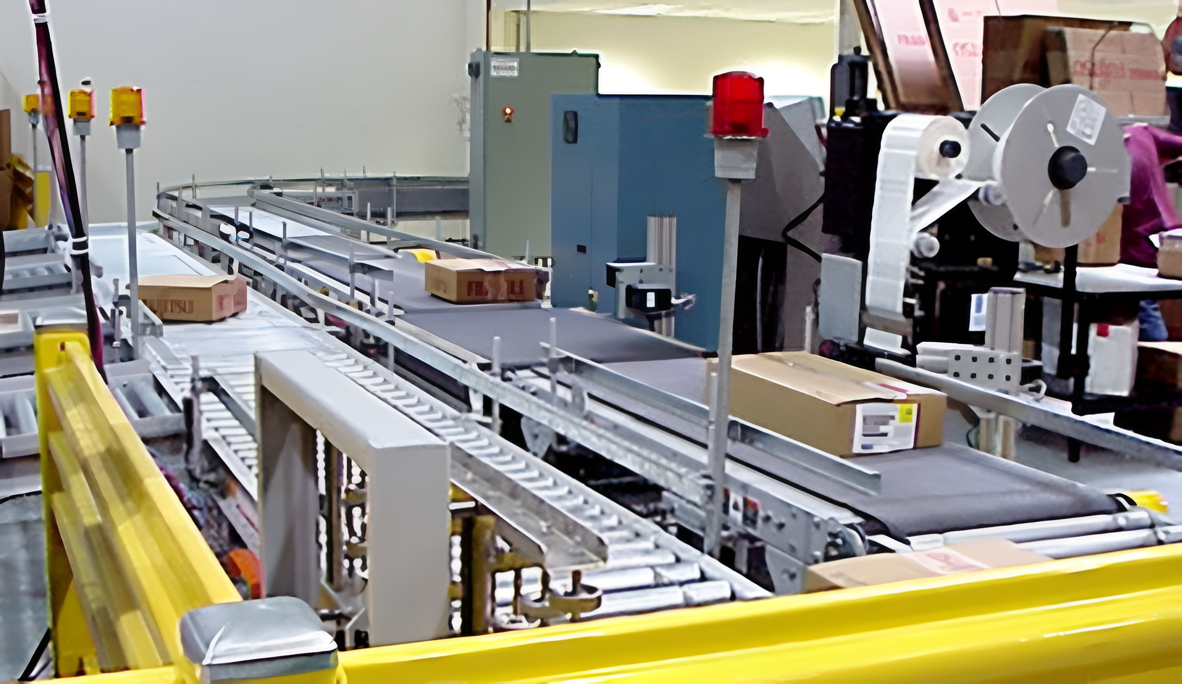
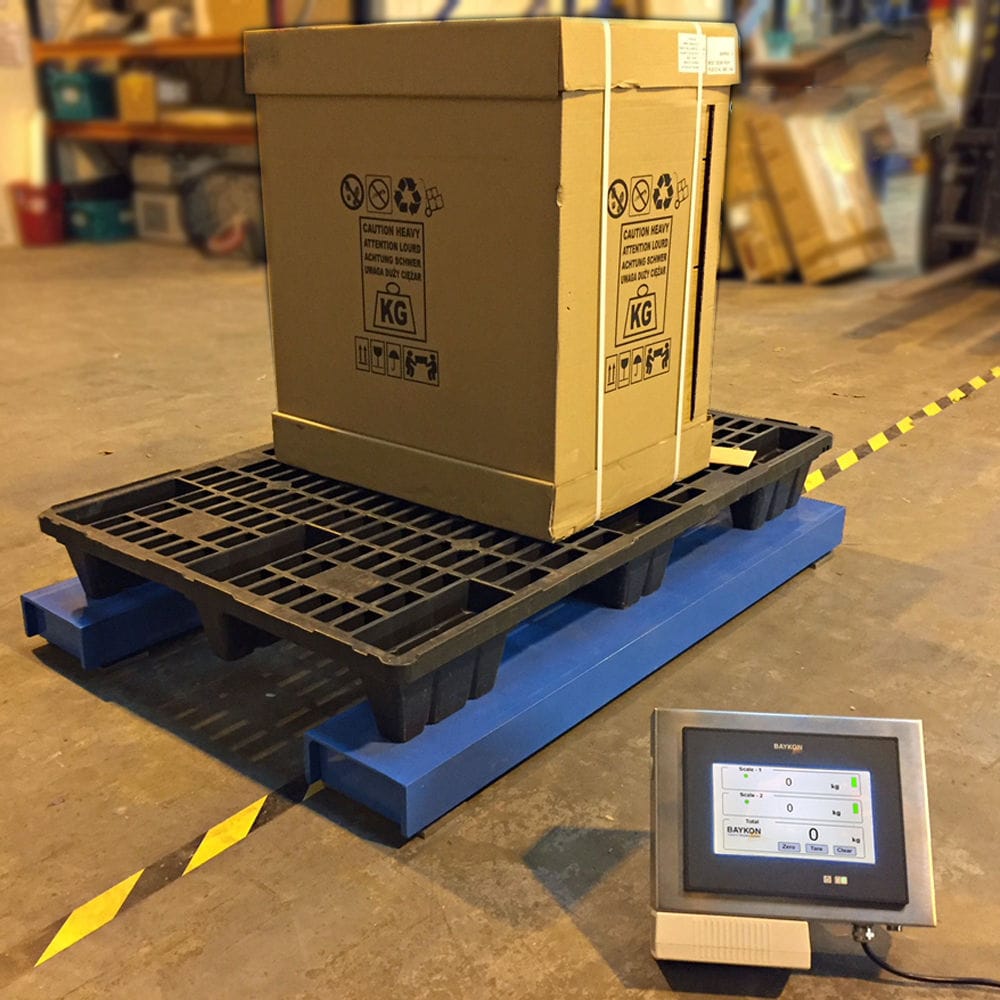


The emulsion filling machine is a specialized equipment for the realization of automatic metering and filling of liquid products, for metering and filling of all types of liquids (fluids, viscous and pasty), with the option of having a spinning system. During operation, only the container needs to be placed at the input end of the transfer system, and the rest of the operation procedures (except for opening and closing the cap) are automated. Automatic filling and dosing of various liquid media can be done accurately.

 020-34563445
The liquid Filling machine adopts an integrated design of automatic linear filling machine and spiral capping machine, with an out of tolerance alarm on the operation interface and dual windows that can display filling volume, number of barrels, cumulative volume, etc. According to the product and the container volume that needs to be filled. After receiving the filling instruction message, the Filling system can perform the filling work within a certain period of time, and the data viewing interface provides two views: offline and online. According to production requirements, when a certain material needs to be delivered on the production line, the production worker presses the control button on the corresponding workstation. The filling system sends the name, workstation number, quantity and other information of the material to the LED screen display through a fieldbus based communication module. At the same time, it starts the music ringtone and lights up the corresponding indicator lights on the workstation and lightbox. After receiving the information, the warehouse staff presses the corresponding button under the light box indicator to respond. The indicator light on the light box for the corresponding material will turn off, indicating that the information confirmation has started feeding. The bus controller changes the indicator light above the workstation button from constantly on to flashing based on the confirmed information, indicating that the material is being delivered. When the material arrives at the calling station, the operator restores the button to the disconnected state, and the indicator light goes out, indicating that the material delivery process is over.
The explosion-proof filling machine adopts a material bucket, a filling head, and a quantitative filling mechanism. Through a quantitative piston valve and a metering filling mechanism, the quantitative piston valve includes a quantitative piston valve body and a telescopic sleeve; The quantitative piston valve body includes a liquid input tube, a liquid output tube, a quantitative piston valve sleeve, and two end plates. The two end plates are respectively installed on the openings at both ends of the quantitative piston valve sleeve. The liquid input tube and the liquid output tube are respectively arranged on the two end plates, and the liquid input tube and the liquid output tube are respectively connected to the quantitative piston valve sleeve. The side wall of the quantitative piston valve sleeve is provided with a metering material inlet and outlet; The expandable sleeve is located inside the quantitative piston valve body, and the edges of the openings at both ends of the expandable sleeve are fixed on the two end panels. The liquid input pipe and the liquid output pipe are respectively connected to the openings at both ends of the expandable sleeve; The measuring and filling institution connects the inlet and outlet of measuring materials through conveying pipes; The outlet of the material bucket is connected to the liquid input pipe, and the liquid output pipe is connected to the filling head. The weighing and filling mechanism includes a measuring liquid storage container and a rotary pump. The measuring liquid storage container is connected to the inlet of the rotary pump through a conveying pipe, and the outlet of the rotary pump is connected to the inlet and outlet of the measuring material through a conveying pipe. The filling machine also includes a driving mechanism, a sliding shaft, a valve body, an inlet pipe, and a ring. The driving mechanism is fixed on the valve body, and the valve body has an inner cavity. The bottom of the valve body has an outlet, and the top of the valve body has a sliding hole. The sliding hole and the outlet pipe are respectively connected to the inner cavity. The inlet pipe is installed on the outer wall of the valve body and is connected to the inner cavity; The top of the sliding shaft is connected to the driving mechanism, and the bottom of the sliding shaft extends into the inner cavity through the sliding hole of the valve body, with the bottom of the sliding shaft located above the liquid outlet; The outer edge of the ring is fixed at the top of the inner cavity, and the inner edge of the ring is fixed on the sliding shaft; One of the two pneumatic ball valves has its inlet pipe connected to the outlet of the material barrel, and its outlet connected to the liquid input pipe of the sanitary quantitative piston valve. The other pneumatic ball valve has its inlet pipe connected to the liquid output pipe of the sanitary quantitative piston valve, and its outlet connected to the filling head.
The driving mechanism of the metering filling machine drives the bottom end of the sliding shaft to descend. When the bottom end of the sliding shaft contacts the bottom surface of the inner cavity, it can block the liquid outlet. Due to the use of a sliding shaft bottom end to block the liquid outlet, there can be a large distance between the ring and the bottom surface of the inner cavity. The ring divides the inner cavity into two parts, with the inner cavity located above the ring being empty, and the driving mechanism and other components located above the ring. The inner cavity located below the ring allows liquid to enter, and after cleaning, the liquid will not remain. Since the function of the ring is not to close the channel, its area can be designed to be relatively small, and both its outer and inner edges can be supported, so the ring can withstand greater pressure. Due to the fact that the liquid enters the inner cavity through the inlet pipe and then flows out through the outlet, the entire flow path is relatively simple and does not have the narrow and angled bends that are commonly found in ordinary valves. Therefore, the resistance experienced by the liquid flow is very small. The ring is located at the top of the inner cavity, and the outlet of the inlet pipe is located on the side wall of the inner cavity. In this way, the liquid flowing out of the outlet of the inlet pipe will not directly impact the ring, which can effectively prevent the ring from being repeatedly damaged by liquid impact for a long time. In order to facilitate the closure of the liquid outlet, the bottom of the inner cavity is provided with a blocking groove that connects the bottom of the liquid outlet. The bottom of the sliding shaft is equipped with a blocking head that can be inserted into the blocking groove and block the liquid outlet. The shape of the blocking head of the quantitative filling machine is the same as that of the blocking groove, and the size of the blocking head is the same as that of the blocking groove. After inserting the blocking head into the blocking groove in this way, the blocking groove can be blocked to achieve the purpose of blocking the liquid outlet, without only blocking the liquid outlet through the bottom end of the sliding shaft.
Basic Parameters:
Maximum weighing capacity: 30kg
Minimum sensitivity: 0.01kg
Filling error: ± 0.01-0.02kg
Filling speed: 20L, approximately 150-180 barrels per hour
Control mode: 2nd gear control
Filling method: Insertion type, above liquid level
Gun head pipeline: PTFE gun head, valve+PTFE hose
Structural material: SUS304 stainless steel for the host, carbon steel for conveying and stacking with anti-corrosion paint.
Scale platform size: 400 × 800mm (304 stainless steel power raceway)
Empty bucket raceway: 400mm × 2500mm (304 stainless steel power raceway) with an additional 1200mm sloping unpowered drum
Heavy bucket raceway: 400mm × 2500mm (304 stainless steel power raceway, 2 sets)
Bucket sorting device: suitable for 20L buckets, carbon steel anti-corrosion paint structure, 304 stainless steel raceway.
Stacking equipment: translation type, suitable for pallets of 1200 × 1200 × 140mm, including pallet supply, palletizing, and lower pallet conveying.
Pipeline pressure: 0.2-0.6MPa (depending on material properties).
Material interface: 4 DN40 flange joints, available according to user provided interface standards
Air source interface: The user provides a 12mm air hose connector for quick connector connection
Power supply: AC220/50Hz (provided by the user to the machine side)
Gas source used: 0.4-0.8Mpa (provided by the user to one side of the machine)
Operating temperature: -10 ℃ -50 ℃
Basic conditions: A sturdy concrete floor with a suspended agent, and the concrete thickness should be greater than 10cm.
Optional models: Standard, Explosion proof Filling