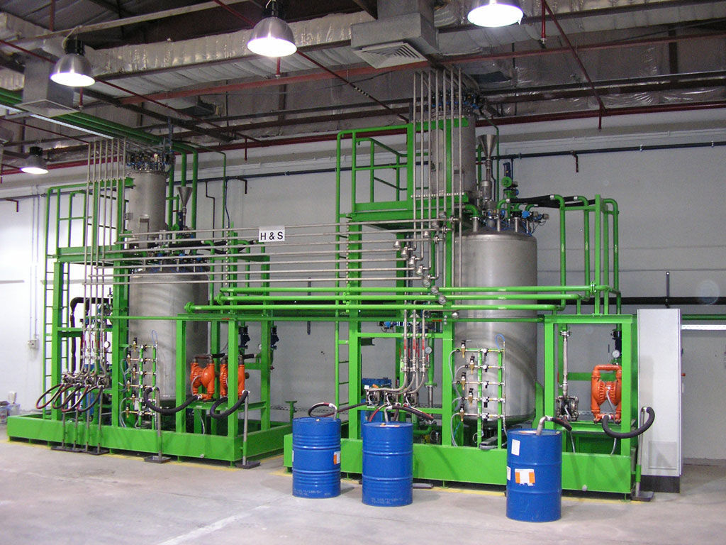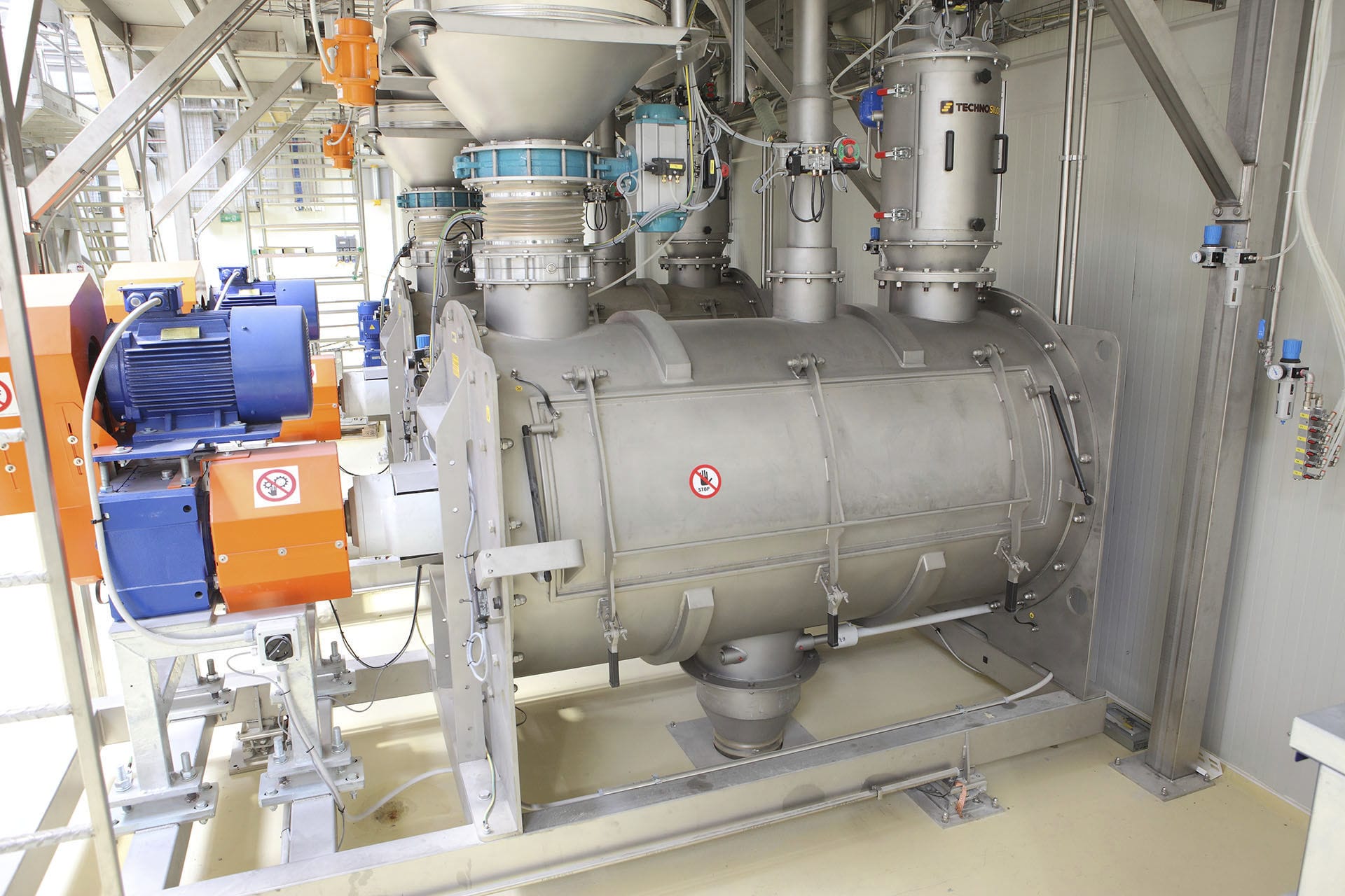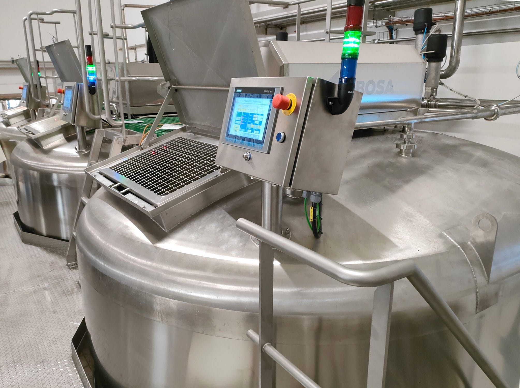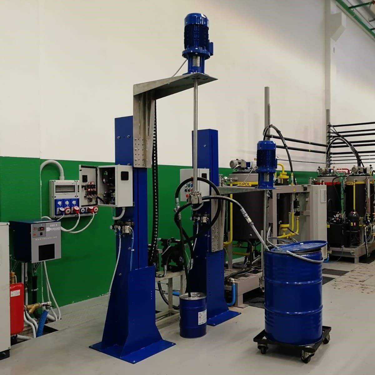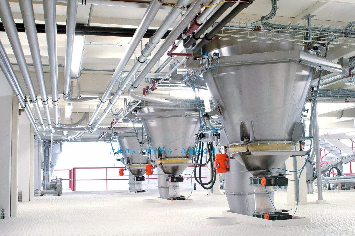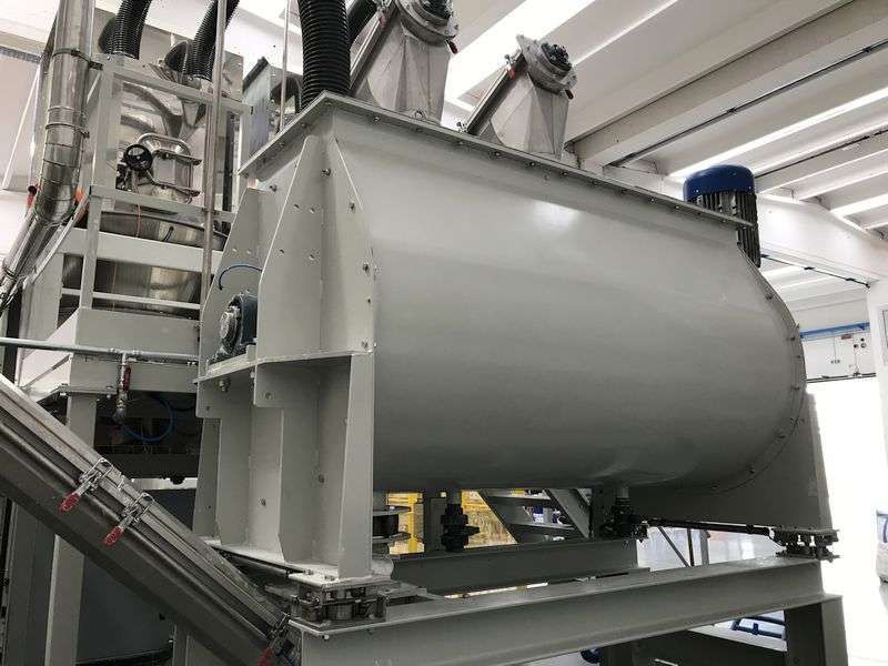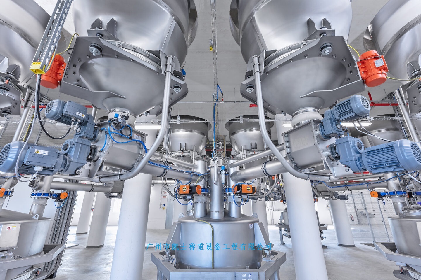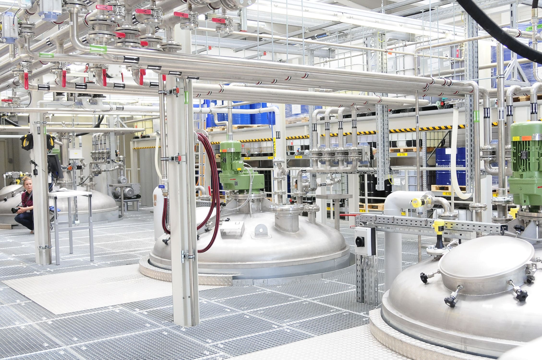




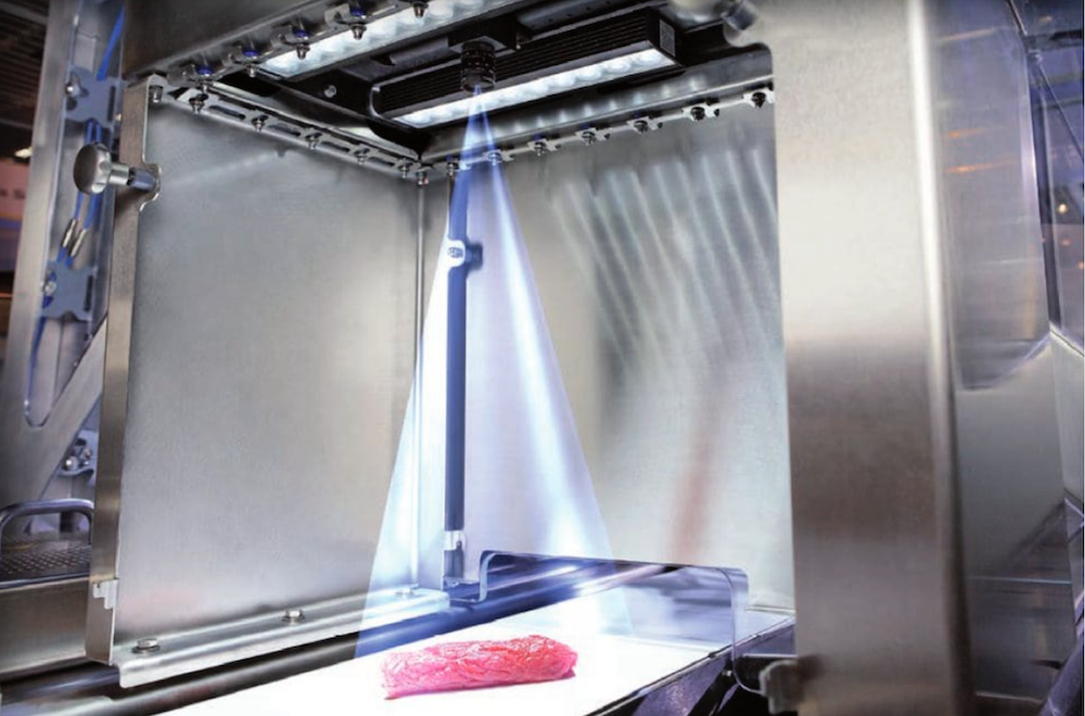
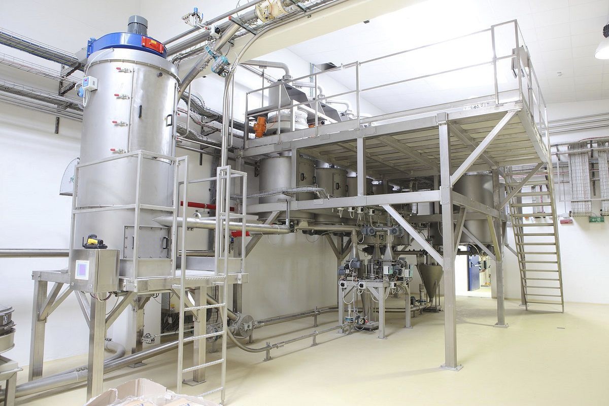


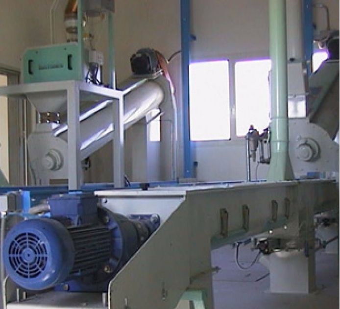
The ingredient conveying system adopts PLC control technology. The core control is a closed-loop control formed by "screw scale - weighing module - PLC - frequency converter". The main equipment includes the screw scale, weighing module, high-speed counting module, PLC, frequency converter, system software configuration software, and the upper computer, etc. After the automatic ingredient dispensing system is powered on, the screw drive motor starts to rotate. The microcomputer controls the motor speed according to the current operation. The materials in the hopper fall into the discharge area and are transported by the screw to the weighing area. The electronic screw scale weighs the materials on the screw.

 020-34563445
The ingredient conveying system is composed of a spiral scale frame, load sensor, speed sensor and spiral Feeder. The main part of the scale frame is formed by one spiral feeder and a counterweight frame. The connection at the bottom of the scale body is achieved through a cross spring group, serving as the support point for the force transmission of the scale. The balance device of the scale frame is adjusted by the counterweight blocks on the counterweight frame. When the material passes through the scale body, the weighing module converts the mass of the material into an electrical signal and inputs it to the amplification unit. After amplification and adjustment, it becomes a 4-20mA standard current signal corresponding to the mass, which is sent to the A/D template input port of the weighing instrument. The A/D template converts the analog signal into a pulse signal (digital signal), which is sent to the PLC for calculation and frequency division processing, thereby obtaining the mass value displayed on the screen. The weighing instrument also outputs a flow signal, which is converted by the D/A template to 4-20mA and sent to the S system to complete the internal closed-loop control of the automatic control system. The S outputs a given analog signal to the weighing instrument, which is converted by the A/D template into a pulse signal (digital signal), and then controlled by the software program and converted by the D/A template to output a 4-20mA analog signal into the frequency converter to achieve the speed regulation of the spiral feeder. In addition, this system can also be controlled directly by clicking on the screen through a keyboard or mouse on-site, which is convenient and easy to operate.
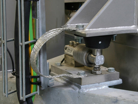
The connection parts between the spiral feeder, the weighing module and the connecting fixation mechanism are welded with reinforcing plates. The upper end of the weighing module and the connecting fixation mechanism are connected to the reinforcing plate by fixed bolts, and the lower end is adjusted in levelness by adjusting positioning blocks and then connected to the frame. The reinforcing plate used is a steel plate with an arc-shaped section or a similar component, which is easy to be welded and ensures that the conveyor has sufficient strength and rigidity. The adjusting positioning blocks used are composed of two blocks with similar triangular cross-sections, which can conveniently adjust the horizontal position of the spiral feeder. The limit position of the spiral feeder is adjusted by fixed bolts, and after the equipment is adjusted, it is welded and fixed. A damping rubber plate is placed between the weighing module and the reinforcing plate to eliminate the vibration influence. The connection parts between the spiral feeder and the supporting mechanism are welded with reinforcing plates. The upper end of the supporting mechanism is connected to the reinforcing plate, and the lower end is connected to the frame. The supporting mechanism is connected by a connecting shaft and rubber bearings. The air guide pipe is installed at the outlet end, one end is connected to the spiral feeder, and the other end is connected to the upper-level feeding mechanism. Rubber bearings are used as the support points, and they are fixed by tightening nuts and bolts to eliminate the influence of the power part.
The automatic Batching system adopts PLC control technology. The core control is a closed-loop control formed by "screw scale - weighing module - PLC - frequency converter". The main equipment includes screw scale, weighing module, high-speed counting module, PLC, frequency converter, system software configuration software, and upper computer, etc. After the automatic batching system is powered on, the screw drive motor starts to rotate. The microcomputer controls the motor speed according to the current operation. The materials in the hopper fall into the discharge area and are transported by the screw to the weighing area. The electronic screw scale weighs the materials on the screw. The weighing module outputs a voltage signal according to the magnitude of the force received, which is amplified by the transducer and output as a measurement level signal proportional to the weight of the materials. This signal is sent to the interface of the upper computer, sampled and converted into a flow signal, which is displayed on the upper computer as the current flow value. At the same time, this flow signal is sent to the PLC interface and compared with the various batching set values in the upper computer. Then, the adjustment calculation is performed, and the control quantity is sent to the frequency converter to change the output value of the frequency converter, thereby changing the output speed of the driving motor to adjust the valve opening of the star-shaped ash discharge valve and adjust the material discharge volume to adjust the given quantity to make it equal to the set value, completing the automatic batching process. The upper computer sets the total flow and the main and auxiliary material ratio parameters, and mixes the remaining auxiliary materials in accordance with the formula ratio. The measurement control combines measurement deviation and frequency speed regulation, and has the advantages of simple structure, good stability, reliable operation, and convenient adjustment.