






The batching system adopts the master-slave structure, with the industrial computer as the upper host and Siemens PLC, frequency converter and weighing instrument as the lower slave. The host is in the dominant position to realize the communication management and control of each slave computer. The RS-232 asynchronous communication interface of the industrial computer is connected to the PLC after the level conversion, forming a physical channel for the communication between the upper and lower computers. Another RS-232 port of the host is connected to the communication port of the weighing instrument to form a second physical channel.


 020-34563445
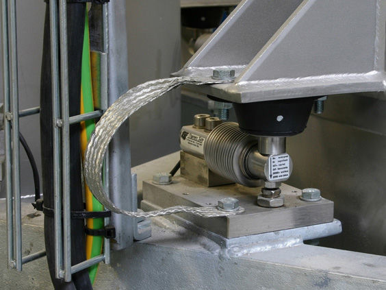
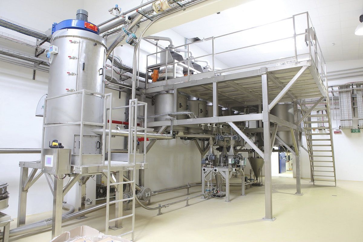
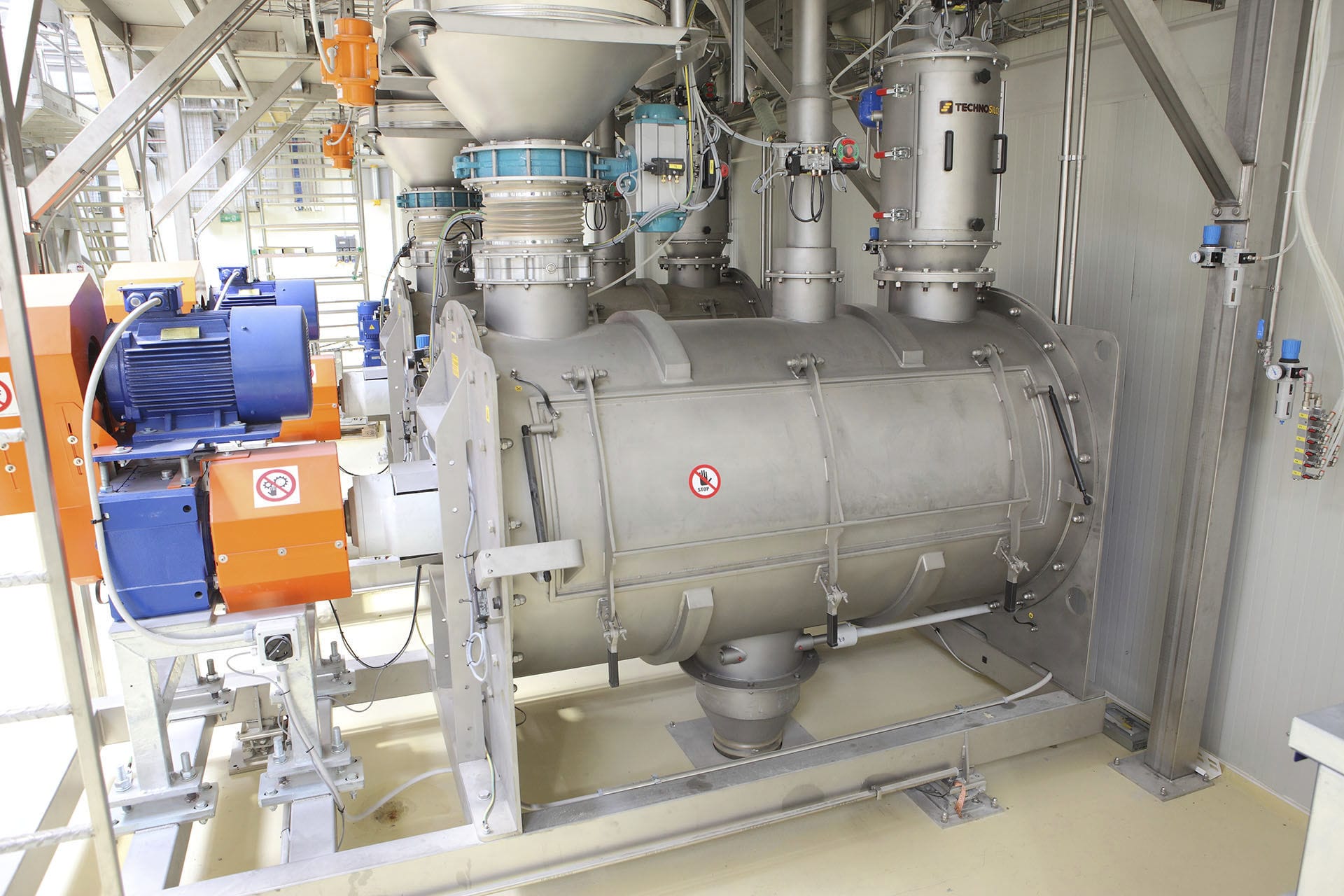
The continuous Weighing system is mainly composed of a hopper machine, an Electronic scale, and an automatic control system. The entire system is installed in a square hopper body. The weighing system includes two hopper scales on the left and right, three Weighing modules, one set of weighing instruments, a material flow switching device, a hopper discharge gate, a cylinder for switching the discharge gate, an electromagnetic valve, an air source component, a control panel, and the automatic control system. When starting the measurement, through the material flow switching device, the left hopper scale is in the feeding state, the right hopper scale is in the waiting state for feeding, after the left hopper scale finishes feeding, it enters the electronic scale weighing state, while the right hopper scale enters the feeding state, to ensure the continuity of feeding. After the left hopper scale finishes weighing, the cylinder controls the discharge gate to discharge the material quickly, and immediately enters the feeding waiting state. After the right hopper scale finishes feeding, it switches to the electronic scale weighing state, the left hopper scale then switches to the feeding state, and this cycle repeats. Through multiple cycles, the entire electronic scale weighing task is completed. During the weighing process, there must always be one hopper scale in the feeding state to ensure the consistency of the precise electronic scale and the continuous material transportation.
The continuous hopper scale is composed of a divider plate, a hopper, an inlet port, and a receiving hopper. The hopper is composed of two hoppers A and B. Each hopper has a pull-out bottom at the lower part, and each bottom is driven to open and close by a motor. When the motor rotates in the forward direction, the lower bottom is opened, and when it rotates in the reverse direction, the lower bottom is closed. The two hoppers take turns feeding and weighing. When one hopper (for example, hopper A) is feeding, continuously detect the mass of the material in hopper A. When the mass approaches the full scale (exceeding the set scale), stop feeding, and the divider plate switches to another position, feeding to the other hopper (B). Before feeding to hopper B and weighing in hopper A, stabilize the weighing to eliminate the vibration caused by the impact of the falling material during feeding. Then weigh the material in the hopper to truly achieve continuous feeding and static weighing. The structure of the divider plate can be divided into two parts: movable and fixed. It is connected by a spiral. The reason for dividing the divider plate into two parts is that if it is made as a whole, during the rotation of the divider plate, the material will fall to the middle of the two hoppers, causing loss. The design of the movable divider plate can solve this problem. One end of the movable divider plate is equipped with a connecting rod, and the lower side of the connecting rod is connected to a spring and the valve. When the valve is not electrified, the divider plate is pulled to one side by the spring through the connecting rod, and the material falls along the divider plate from the discharge port to hopper A; when the valve is electrified, the valve clamps, pulling the divider plate to the other side, and the material falls along the divider plate from the discharge port to hopper B, thereby achieving the alternate feeding of the two hoppers.
The continuous weighing system uses mutually backup weighing devices to reasonably switch during the electronic scale and feeding, discharging, etc. processes, so that the weighing device has one device in the feeding state and another device in the auxiliary state of the electronic scale to ensure the continuity of the material flow and the accuracy of the electronic scale. The timing sequence of material flow switching and the state transition of the two sets of weighing devices ensures that the sum of the electronic scale time and discharge time of one device is less than the longest feeding time of the other device. Otherwise, the feeding hopper in the electronic scale feeding state is full, and the hopper scale has not completed or discharged yet, then it cannot be switched to the feeding state, and the continuity of the material flow cannot be guaranteed. The longest feeding time is determined by the measurable maximum flow rate and the effective volume of the hopper scale. The weighing time is determined by the stable delay time during measurement. The discharge time of the hopper scale is determined by the cross-sectional area of the discharge port and the falling speed of the material. Since the weighing instrument selected for the weighing system is a digital type, the weight data has already been converted into digital form within the instrument. If it is transmitted to the PLC using analog signals, the instrument needs to perform D/A conversion. The PLC needs to add an analog input module and then undergo A/D conversion to convert the analog quantity into digital form. This not only increases the cost but also reduces the accuracy of the electronic scale due to multiple conversions. Therefore, a serial communication method is adopted to directly transmit digital quantities. The serial communication of the weighing instrument generally uses the RS-485 method, with the communication protocol being MODBUS. However, many PLCs do not have software modules that directly support the MODBUS protocol. Therefore, it is necessary to implement communication with the instrument using PLC programming. To ensure the reliability of the communication, effective anti-interference measures must be adopted, including shielding of communication lines, terminal resistors, and the use of data retransmission and software fault-tolerant algorithms, etc.