


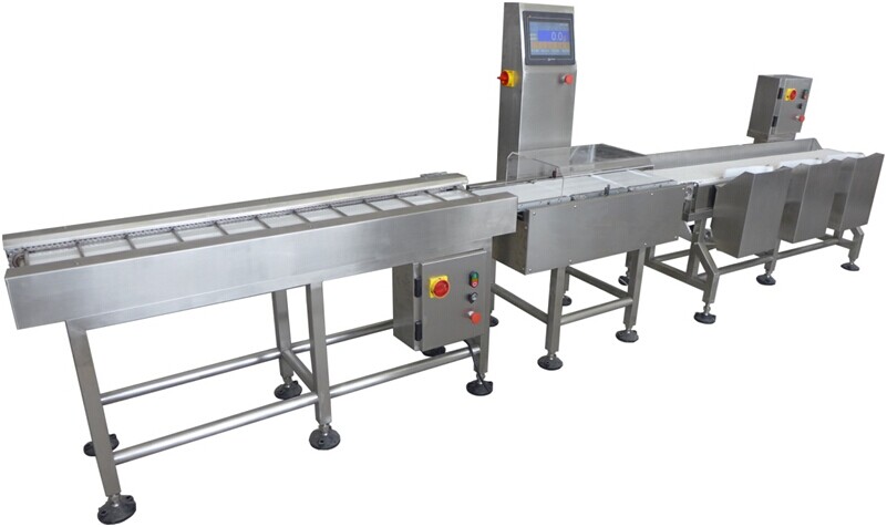
The Dynamic sorting machine is mainly composed of feeding part, weighing part and sorting part. For the heavy products waiting for inspection in line, the running speed is increased through the feed belt to ensure that there is sufficient spacing between the products to avoid having two products on the weighing table at the same time. After the product enters the weighing table, the system identifies the product to be detected into the weighing area according to external signals (photoelectric, threshold). The weighing part completes the collection of weight signal, and sends the weight signal to the controller for processing, and obtains the dynamic weight value of each product. The sorting part is used to transport the finished product out of the weighing area and to eliminate the product with unqualified weight. According to the shape and weight of the product, the way to remove air blowing, pushing rod, flipping plate, etc.

 020-34563445
Real-time control system for the grading and discharging process of the dynamic Sorting machine. A continuous dynamic registration method for product grade information and product real-time position is proposed to achieve real-time detection, continuous tracking of the product flow on the conveyor line, continuous dynamic registration of product grade information and its real-time position, and automatic control of the product grading and discharging process. The circuit structure of the control system is given, the control process of the stepper motor is analyzed, and the actual operation experiments show that under the control of this system, all products can be automatically and smoothly discharged at the entrance and exit of the determined grade by the detection device.
The weighing machine uses a continuous dynamic automatic weighing method to test the weight of items, combined with an automatic sorting mechanism, to achieve high-speed and high-precision weight inspection and sorting on the production line. According to the weight that meets the customer requirements, the sorting process can be realized. This can reduce the labor cost of the sorting process and optimize the production process. The sorting scale is actually an electronic device that can display the weight digitally, store, count, and print the weight data. In modern intelligent production, the application of such devices is very extensive and has received widespread attention and recognition.
The weighing machine can sort and test packaged items in different environments and can also test the weight of the products. The weight sorting scale is controlled by an electronic computer. It can monitor the weight, accuracy, sealing performance and quality of the products. The result of computer control is that the packaged items are decomposed into several small components in the environment, so as to achieve the purpose of cost reduction and rate increase. The automatic detection equipment can automatically sort, test and process the bags through computer technology and network technology, making the detection process more convenient.
The weighing machine uses a dynamic weight signal processing system, rich software, electronic and mechanical accessories, so this series can meet the online inspection requirements of various industries. The modular design makes the operation and daily maintenance of this series very simple. The product components are easy to disassemble and clean with water, use imported electrical components, have waterproof performance, and the operation surface is simple. It can store parameters of 100 different weight specifications of materials, which is convenient for operation and use. Built-in report statistics, reports can be generated in EXCEL format, can automatically generate various real-time data reports, and the U disk can store statistics for more than one year, allowing you to grasp the production status at any time.


