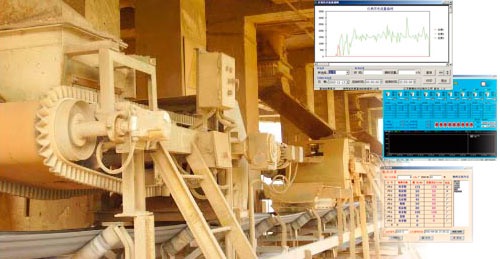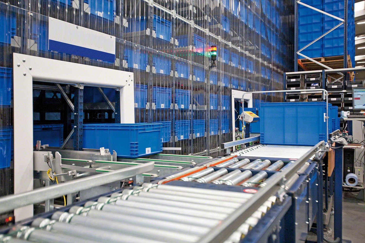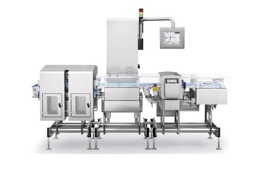


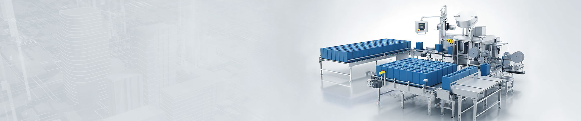




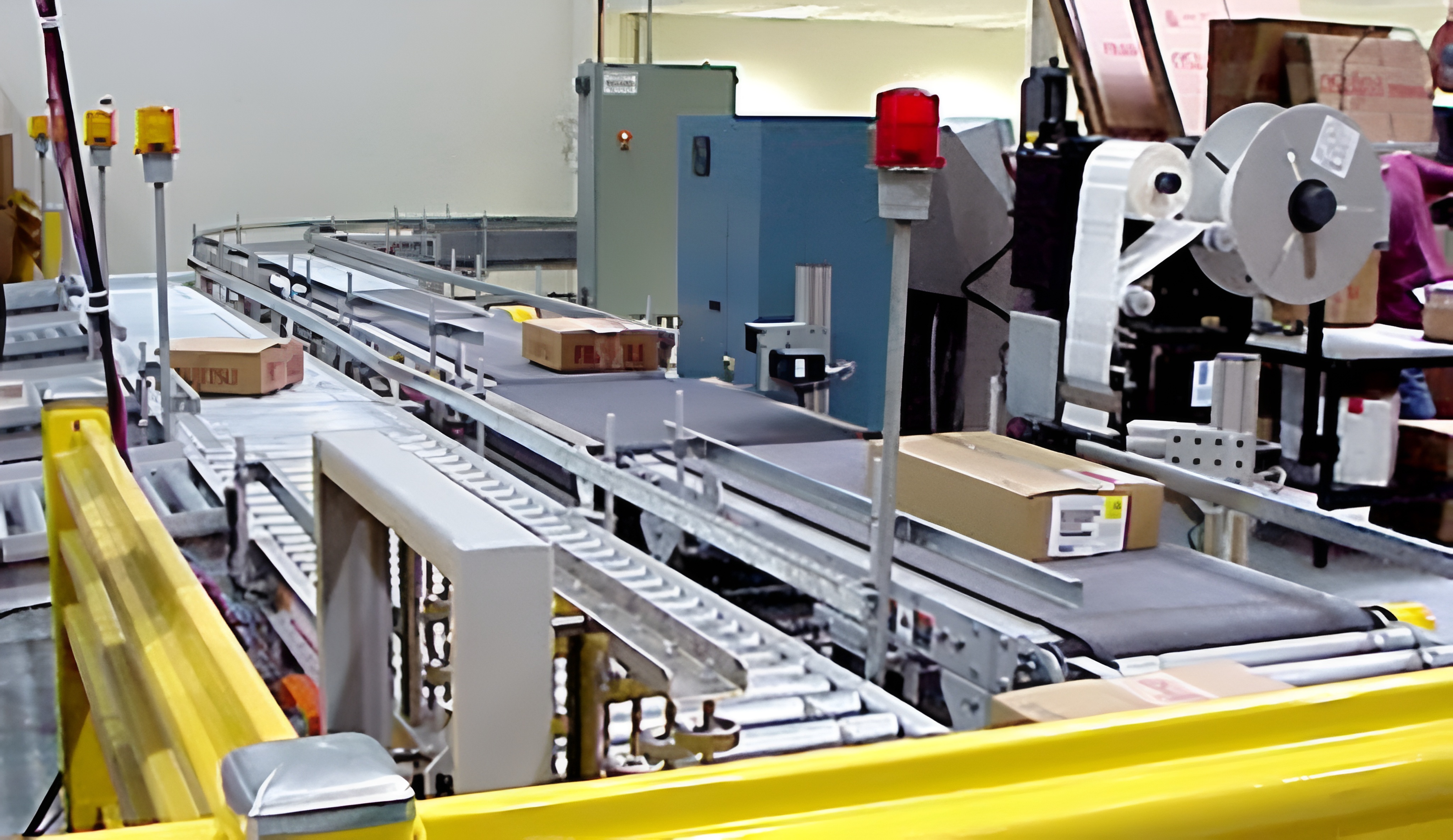
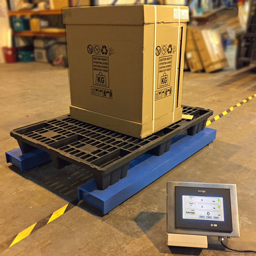


Frequency Conversion Belt Weigher is a series of machines and equipment that use intelligent technology such as computer to detect and analyze the controller and get accurate weighing information content. It is used for automatic continuous weighing of bulk solid materials transferred on belt conveyors. It can accurately measure the instantaneous and cumulative total flow of materials transported on the belt conveyor in the material transportation link. The key components are weighing bridge, weighing sensor, speed sensor and weighing display indicator value.

 020-34563445
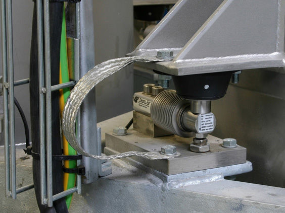
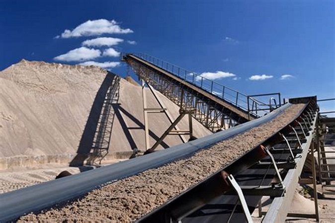
The variable frequency belt scale is a system in which the weight of materials on a conveyor belt is linearly applied to a weighing module through a scale frame, causing a slight strain in the strain sensor. This results in a change in the resistance of the strain gauges on each arm of the bridge attached to the strain sensor. Under the excitation of the bridge voltage, an unbalanced potential output is generated. At the same time, the speed sensor measures the speed of the belt operation, and these two signals are sent to a microcomputer integrator for a series of calculations to measure the instantaneous flow rate of the material. This form is the most basic and widely used belt scale, which receives analog signals from Weighing modules and speed sensors in the system. After integration, it displays instantaneous and cumulative flow rates, and at the same time sends the instantaneous flow rate as a 4-20mA analog current signal to the computer system as an input signal. The computer compares the signal with the set value and outputs a 4-20mA analog current signal. The speed of the feeding motor is controlled by a frequency converter to achieve closed-loop control of the material feeding flow rate, ultimately keeping the instantaneous and cumulative flow rates of several materials within the range required by the feeding process. The belt scale consists of a load-bearing device, a weighing module, a speed sensor, and a weighing display. The load-bearing device is responsible for weighing the objects on the belt and transmitting the data to the weighing module. The weighing module converts this value into a corresponding voltage signal according to a certain conversion formula and processes it into a digital quantity A, which is then transmitted to the arithmetic unit. The speed sensor outputs a pulse number B after receiving the speed of the objects transmitted on the belt and transmits it to the arithmetic unit. After receiving the data, the arithmetic unit performs arithmetic processing to obtain the total amount of objects in a measurement cycle. By counting and accumulating each measurement, the total amount of all objects passing through the belt scale can be obtained.
The belt scale adopts a frame, a conveyor belt, a pulley, and a transmission motor. Two pulleys are rotatably connected to the frame, and the conveyor belt is wound around the two pulleys, forming two layered upper and lower belts with opposite transmission directions. The transmission motor drives the pulley to rotate, and also uses a weighing wheel, a weighing sensor, a speed measuring wheel, a scraper, a cleaner, a tension roller, a limit wheel, and a sliding plate. The weighing wheel is installed on the weighing sensor and contacts the lower end surface of the upper belt. The speed measuring wheel is rotatably connected to the frame and contacts the upper end surface of the lower belt. The speed measuring wheel is connected to the transmission motor and controls the speed of the transmission motor. The skateboard is connected to the frame by sliding, and the tension roller and two limit wheels are both rotatably connected to the skateboard. The tension roller is in contact with the upper end surface of the lower belt, and the two limit wheels are located on the front and rear sides of the lower belt. The cleaner is hinged to the skateboard, and the cleaner is in contact with the upper end surface of the lower belt. The scraper is supported by floating on the frame, and the scraper is in contact with the upper end surface of the lower belt. There are two sliding rails on the rack and located in the conveying direction of the conveyor belt. The sliding plates are connected to the two sliding rails, and there are locking screws on the sliding plates to fix them to the sliding rails. The front and rear sides of the skateboard are hinged with adjustment arms, and the cleaner is hinged on the two adjustment arms. The cleaner is a triangular plate structure, and the top corner of the cleaner is set towards the transmission direction of the upper belt. The adjustable arm is a telescopic structure, using a sub rod, a mother rod, and fixing screws. The sub rod is inserted into the mother rod, and the sub rod is fixedly connected to the mother rod through fixing screws. The sub rod is hinged to the skateboard through bolts, and the mother rod is hinged to the cleaner through bolts. The skateboard is fixed with mounting arms on both sides, and roller seats are fixed on each mounting arm. The tension roller is rotatably connected to the two roller seats. The upper end face of each roller seat is fixed with an adjustment column, and several adjustment holes are layered on the adjustment column. The adjustment column is inserted into the installation arm, and a screw is threaded on the installation arm. The screw is threaded into an adjustment hole on the adjustment column. The side of each roller seat is hinged with an installation plate, and the limit wheel is rotatably connected to the installation plate. The rotation direction of the limit wheel is perpendicular to the rotation direction of the tension roller.