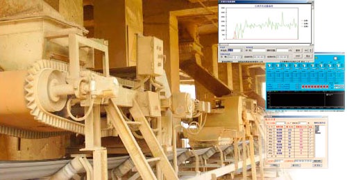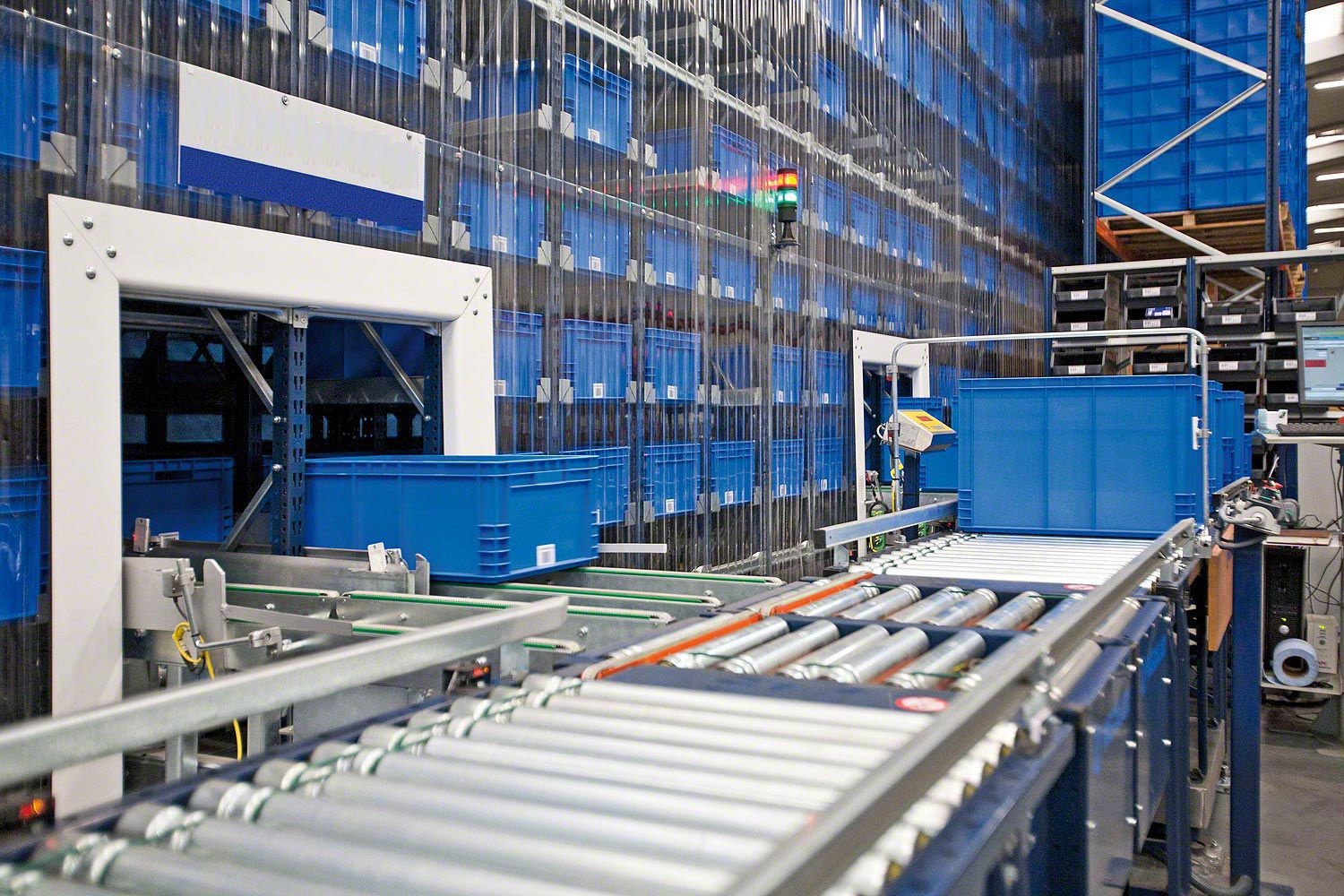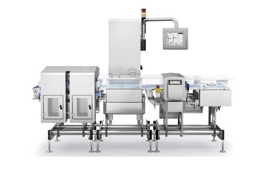











The Continuous belt weigher is used for quantitative feeding of bulk materials. During the feeding process, the belt is continuously fed. The feeder transports the materials from the user's feed bin or other feeding equipment and conducts weight detection through the weighing bridge. The measured weight signal and the speed signal are sent to the integrator for differential processing and display the instantaneous flow rate in tons per hour for comparison, and according to the output of the corresponding signal value (PID signal), the speed of the motor is changed by the frequency converter to change the feed amount, so that it is certain with the set value, so as to complete the control of the constant feed flow.


 020-34563445
The continuous belt scale uses an analog weighing module to convert the measured weight parameters into analog voltage or analog current. It synchronously detects the instantaneous speed of the conveyor belt passing through with a speed sensor and transmits it to a digital transmitter. After being converted by the digital transmitter, the output digital signal is sent to the intelligent weighing controller of the leather belt scale. The instantaneous flow rate and cumulative weight of the material are converted and displayed by the integration principle microcomputer. The measurement signal is transmitted to the control system through a current isolation module to complete the dynamic process of remote display and production process control. The electric control system is composed of a main console, a frequency conversion cabinet, a PLC host, a detection device and a drive device. The main console uses a technologically advanced and reliable programmable controller coupled with a weighing module position sensor and other detection devices to drive rollers, sweepers, etc. The drive component uses a high-performance vector control inverter to control the motor to complete various functions such as stacking, blanking, soft start, soft stop, speed regulation, etc. during the operation of the belt conveyor. Equipped with status display, a weighing sensor is installed under each section of the belt. When the coal on a certain belt exceeds the limit value, the corresponding pressure switch is closed to provide a signal to the PLC for material stacking processing through program analysis, and the overload status is displayed. Install position switches on the left and right sides of the belt. Once the belt deviates, the position switches will be triggered to close. Similarly, the PLC will analyze and drive the correction device of the drum for automatic correction. Install a coal level detection device at a certain height on the ground. As long as the fallen coal reaches this height, the height position switch will close and the PLC will drive the cleaner to clean it.
The weighing bridge of the belt scale is installed on the conveyor frame. When the material passes through, the roller detects the weight of the material on the conveyor belt and acts on the weighing module through a lever, generating a voltage signal proportional to the load of the conveyor belt. At the same time, the speed measuring wheel detects the speed of the conveyor belt. The measured weight signal and speed signal are sent to the weighing instrument integrator for differential processing and display the instantaneous flow rate in tons per hour for comparison. The corresponding signal value (PID signal) is output based on the deviation size. The instantaneous flow rate of the material measured by the weighing belt conveyor depends on two parameters, that is, the instantaneous flow rate is equal to the load value of the material on the carrier measured by the weighing module and the belt speed value measured by the speed sensor=the product of the two parameters. The tripod includes two diagonal support rods and one vertical support rod, and the connecting plate is welded or riveted to the inside of the weighing bridge. By coordinating the installation of the rod body, tripod, connecting plate, and X-frame, three rollers are specifically installed on the rod body. In order to prevent the rollers from deforming the rod body and ensure that the rollers are tightly attached to the conveyor belt, a tripod is set up. The tripod has stability, making the rod body less prone to deformation and ensuring that the rollers can tightly adhere to the conveyor belt, ensuring weighing accuracy. The combination of the connecting plate and the X-frame effectively improves the bending resistance of the weighing bracket, making its own structure balanced and stable. Even if the weighing bracket is loaded for a long time, it is not easily deformed, effectively ensuring the weighing accuracy of the material.
The Weighing system control can start and stop independently, with pressure overload and alarm functions, power frequency frequency conversion switching function, belt deviation handling function, automatic tripping to power frequency function in case of abnormalities, and automatic material cleaning function. The main circuit of the belt conveyor electrical control system has two independent 10kV power supply lines, which are divided into two paths through the busbar for voltage transformation. The 1 # transformer is a 10kV/380V type, which supplies power to the frequency converter. Each frequency converter has a power frequency/frequency conversion switching function (such as in frequency converter 1. KM11 K12 controls the frequency conversion work and KM13 switches to power frequency operation), and then connects to the motor for control. The 2 # transformer is a 10kV/380V type, which supplies power to the PLC cabinet or process control through low-voltage distribution.
Main technical parameters:
System accuracy:+/-0.125%
Weighing range: 1~8000t/h
Belt width: 500~2400mm
Belt speed: 0~4m/s
Belt conveyor inclination angle: ≤ 6 degrees (special materials ≤ 10 degrees)
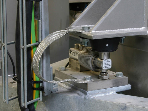
Pull type electronic strain gauge weighing sensor:
Shell: "S" type sealed protection
Nonlinear:<0.03% FS
Non repetitive:<0.01% FS
Creep:<0.02% FS
Zero point output: ± 1%
At maximum flow rate, the displacement of the force application point of the sensor elastic body shall not exceed 0.2mm
Temperature sensitivity: Interval: 0.0008% FS/OF Zero point: 0.0015% FS/OF
Lag error: 0.02%
Sensitivity error: ± 0.1%
Overload capacity: 150% of sensor capacity
Speed sensor:
The speed sensor is installed on the tail drum, speed drum or speed roller, and the speed drum/roller is installed on the upper surface of the return belt, eliminating the impact caused by belt slippage. The speed sensor is a digital brushless pulse generator. When the belt is running, the speed sensor emits a series of speed pulses, each pulse representing a unit length of the belt travel. The pulse frequency is proportional to the belt speed.
The shell material is cast aluminum, which can adapt to outdoor working environments.
The communication pulse generator does not require adjustment or replacement of the carbon brush.
ZKB-60 weighing instrument
Preparation: better than 0.05%
All digital operation, panel operation, key input, simple and convenient
It has functions such as automatic zero adjustment, automatic interval, fault diagnosis, power outage data maintenance, etc
Featuring unique electronic calibration, chain code calibration, hanging code calibration, and physical calibration, among other verification methods
Optional remote counting function with optional multi-point display
Accumulated weight display output: eight digits with decimal point, minimum display 0.01t
Flow display output: four digits with decimal point, unit: ton/hour, or kilogram/hour
Analog output: 4-20mA or 0-20mA current output proportional to flow rate
Communication interface: optional RS-485 or RS-232 serial port