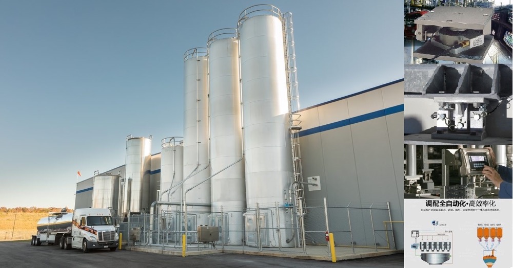






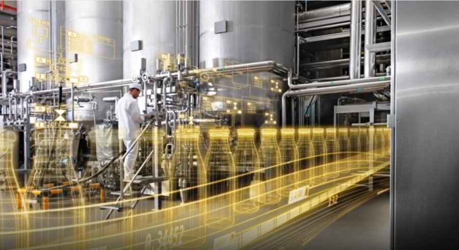
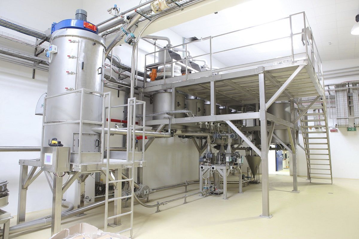
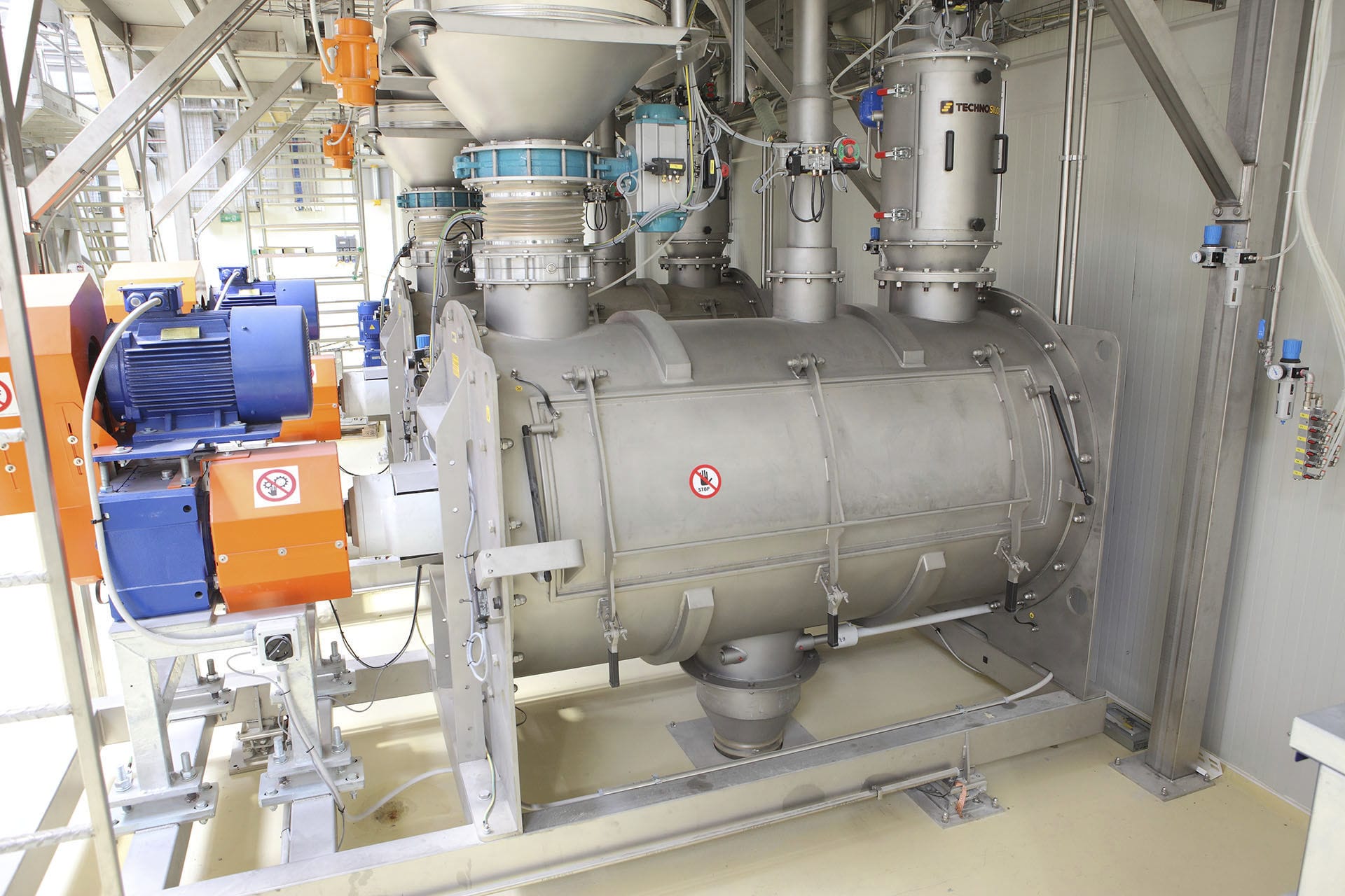
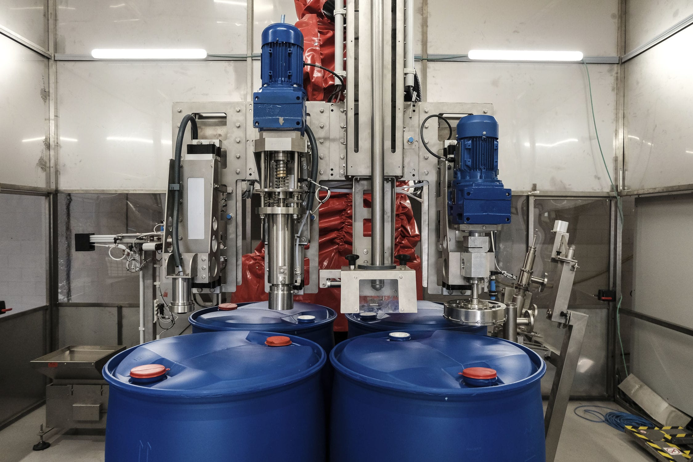


The weighing vacuum feeder adopts the Siemens MMI software WINCC. The system is mainly divided into four screens: process flow screen, parameter setting, centralized control, trend curve and report. Above the clock, there are numerical displays of the total pressure of the gas path and the temperature of the cooling water. In addition, in the process flow, there are main material feeding unit, batching unit, vacuum feeding unit, mixing unit, finished material unit, pulse valve parameter setting, weighing instrument parameter setting, temperature alarm limit setting, motor current display, valve summary control, and temperature alarm curve graph.


 020-34563445
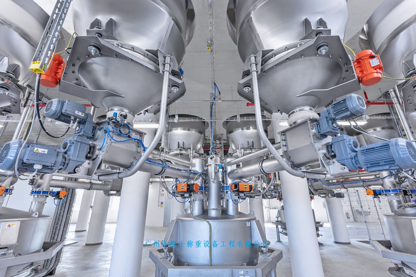
The weighing vacuum Feeding machine scheme takes the vacuum feeding machine as the control unit, and sets the formula setting boundary for different formula feeding and conveying in each vacuum feeding machine, flexibly responding to the needs of different production batches and formulas. The formula, feeding, and discharging are all controlled by computers. In addition to the hopper, the scale body includes a dynamic weighing module, precision amplifier, analog-to-digital converter, microcomputer, display, printer, and execution system. The touch screen control system can control multiple mixers and regulate the time of dry and wet mixing. It can prepare several to dozens of materials, display the ingredient process, and print the names, quality, total quality, cycle time, formula, daily report, monthly report, etc. of each material simultaneously. The loading system provides rich software and easy program modification, making it a highly automated product. By using weighing instruments or touch screens, the required weight of various materials can be set, and then automatically transported to the batching machine by the winch in order for weighing and flow control, thereby achieving precise measurement and batching.
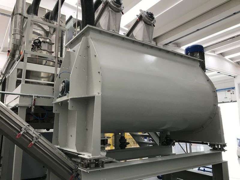
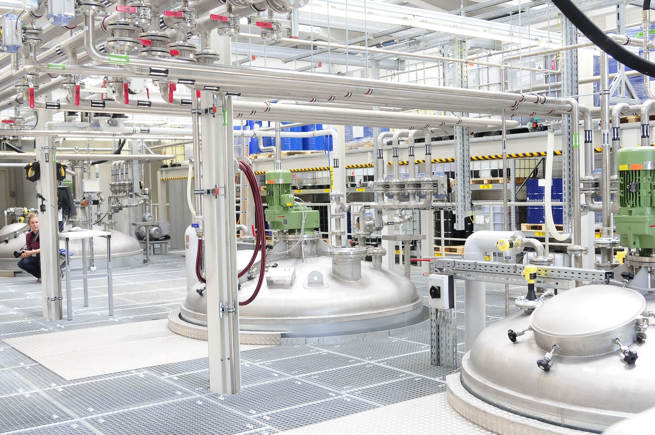
The weighing and feeding machine includes a hopper scale and a support. The hopper scale is set on the support and is welded and fixed to the support. The support consists of four evenly distributed support legs, and horizontal reinforcement ribs are also connected between each pair of support legs to enhance stability. The upper part of the left wall of the hopper scale is equipped with a feeding port, which is also connected to the feeding hopper. The feeding hopper is inclined at an angle of 10-45 degrees, which facilitates the automatic entry of materials into the hopper scale for centralized processing. The hopper scale is also equipped with a vertically distributed spiral mixing and conveying device, which includes a mixing shaft and a spiral blade set on the mixing shaft. The hopper scale is a cylindrical structure, and the feeding hopper is inclined at an angle of 10-45 degrees. The outer diameter of the spiral blade should be kept consistent to ensure the stability of the spiral mixing and transportation, The upper end of the mixing shaft is connected to the top wall of the hopper scale, and the lower end is connected through a support rod, which is horizontally fixedly installed at the bottom of the hopper scale. The input end of the spiral mixing and conveying device is also rotatably connected to a first motor, which is fixedly installed on the upper surface of the hopper scale.
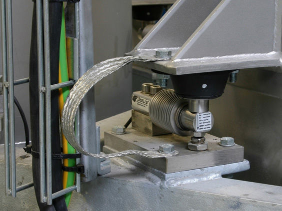
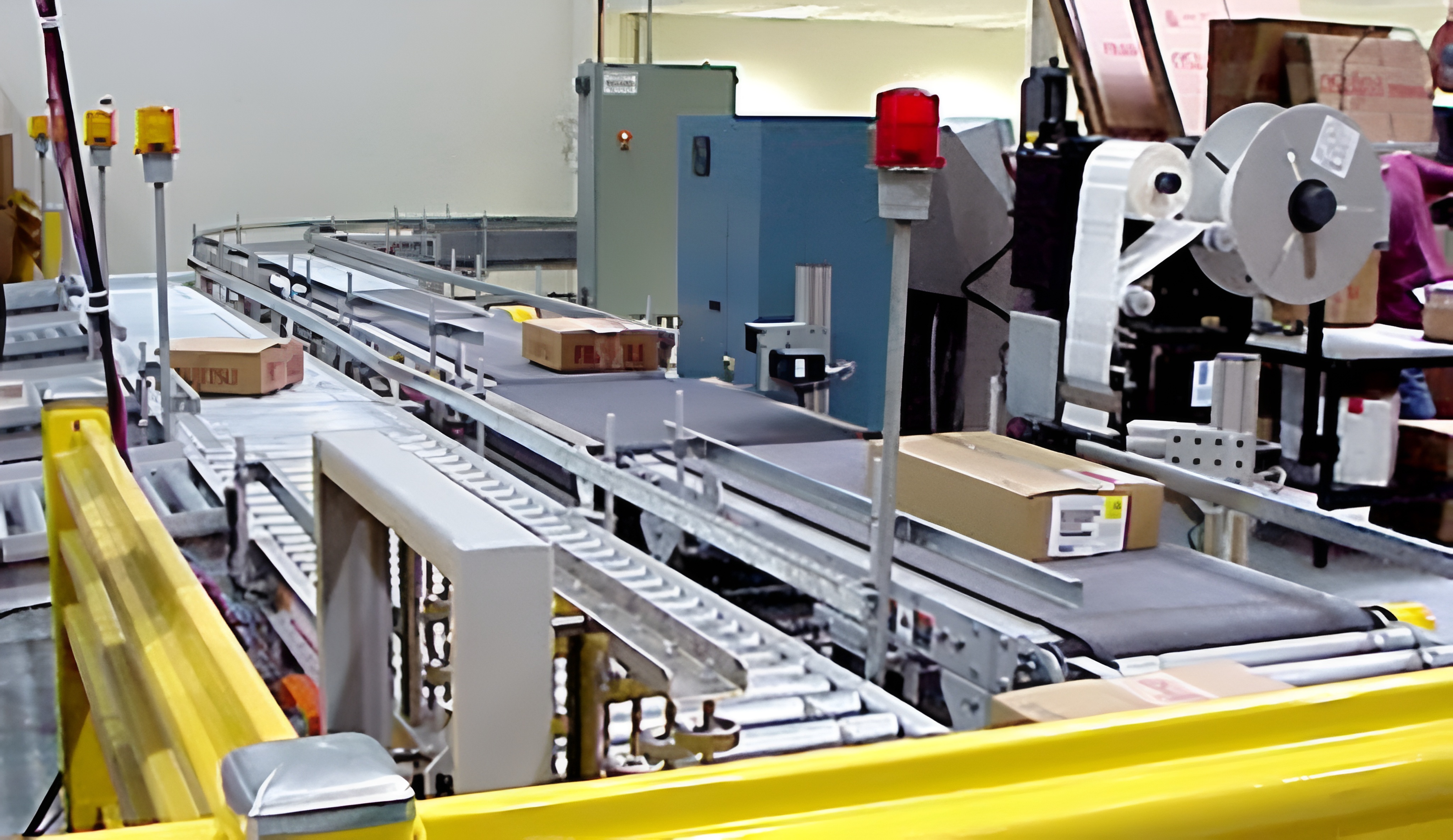
There is also a scale compartment connected below the hopper scale. The upper end of the Electronic scale compartment is connected to an opening and closing plate through a rotating shaft, and the lower end is connected to a weighing plate through a rotating shaft. The bottom of the opening and closing plate is also connected to an inclined telescopic mechanism. The bottom of the telescopic mechanism at the opening and closing plate is fixed to the side wall of the explosion-proof scale compartment. The telescopic mechanism is an electric hydraulic telescopic rod and is symmetrically distributed in two groups. The telescopic mechanism drives the opening and closing plate to achieve opening and closing operations. There are also four Weighing modules evenly distributed at the four corners inside the weighing plate. There are connecting ears on both sides of the weighing plate. There is also a side wing plate on the left side wall of the hazardous waste scale compartment. There is an inclined telescopic mechanism between the side wing plate and the connecting ear. The telescopic mechanism is an electric hydraulic telescopic rod. And the telescopic mechanism is symmetrically distributed in two groups, There is also a conveyor frame and a support column set below the double-layer weighing bin. The two sides of the conveyor frame in the width direction are respectively connected to the driving shaft and the driven shaft, and a second motor is also connected to the driving shaft. There is also a conveyor on the conveyor frame located between the driving shaft and the driven shaft. There are two inclined protective plates on the conveyor frame in the length direction of the conveyor. The protective plates are installed on the conveyor frame through brackets at an angle, and there is a gap between the bottom of the protective plate and the conveyor. This setting ensures the normal transmission of the conveyor and prevents the falling materials from scattering and not concentrating, greatly improving the speed and efficiency of material transportation. On the outer wall of the hopper scale, There are also fixed control switches installed, which are respectively connected to the first motor, the telescopic mechanism The weighing module is electrically connected to the second motor, and there is also an LED LCD display screen on the outer wall of the hopper scale. The LED LCD display screen is electrically connected to the control switch and the weighing module, respectively.