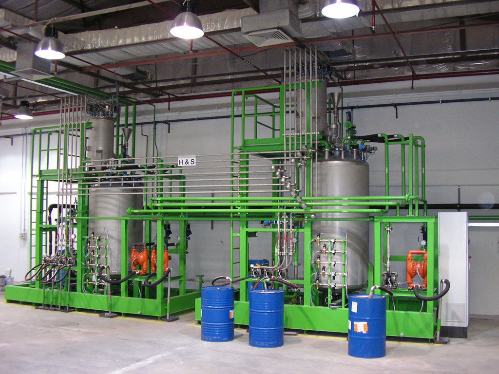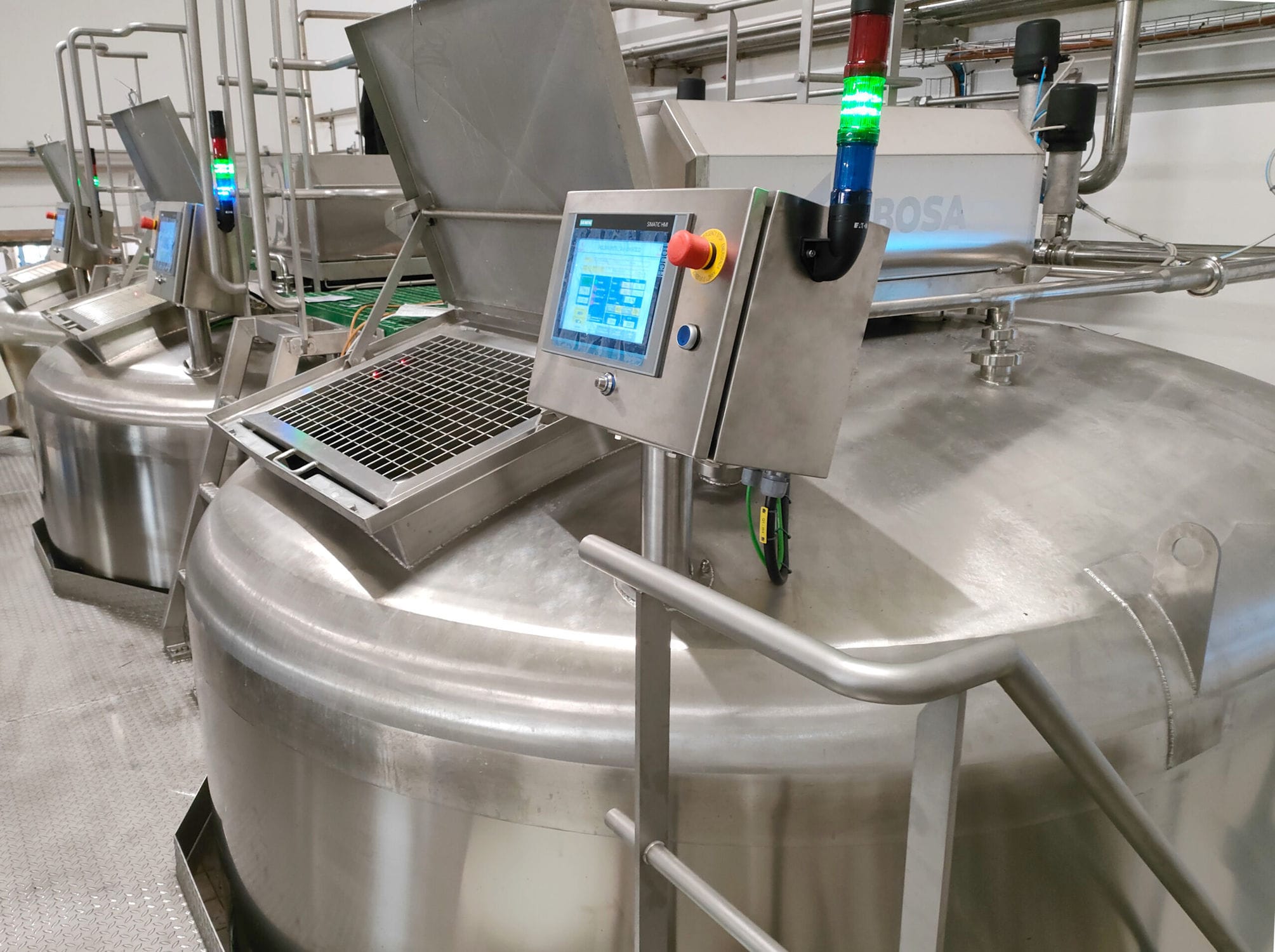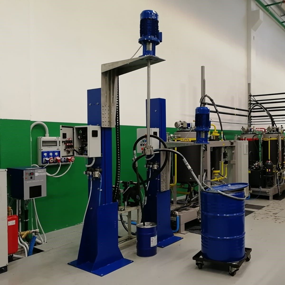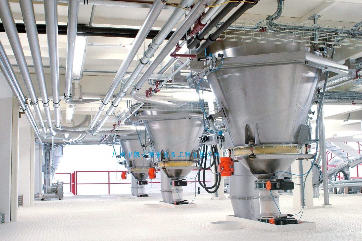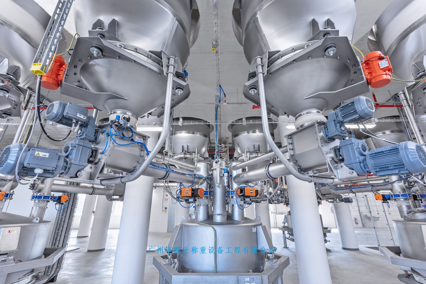




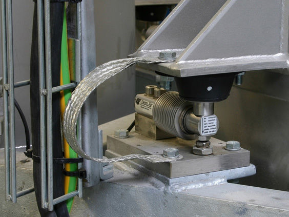
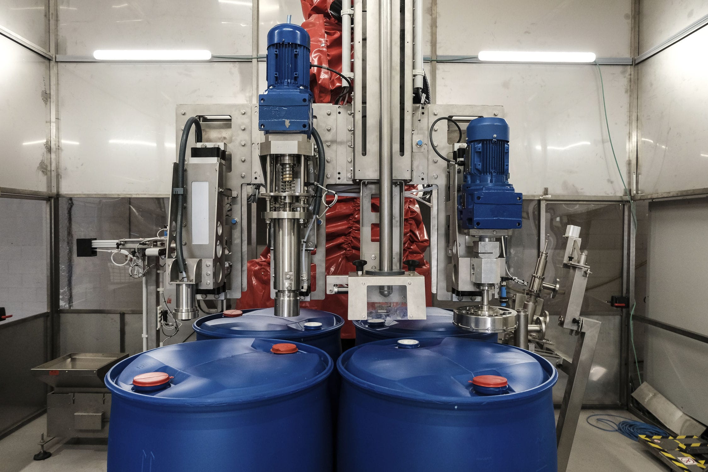
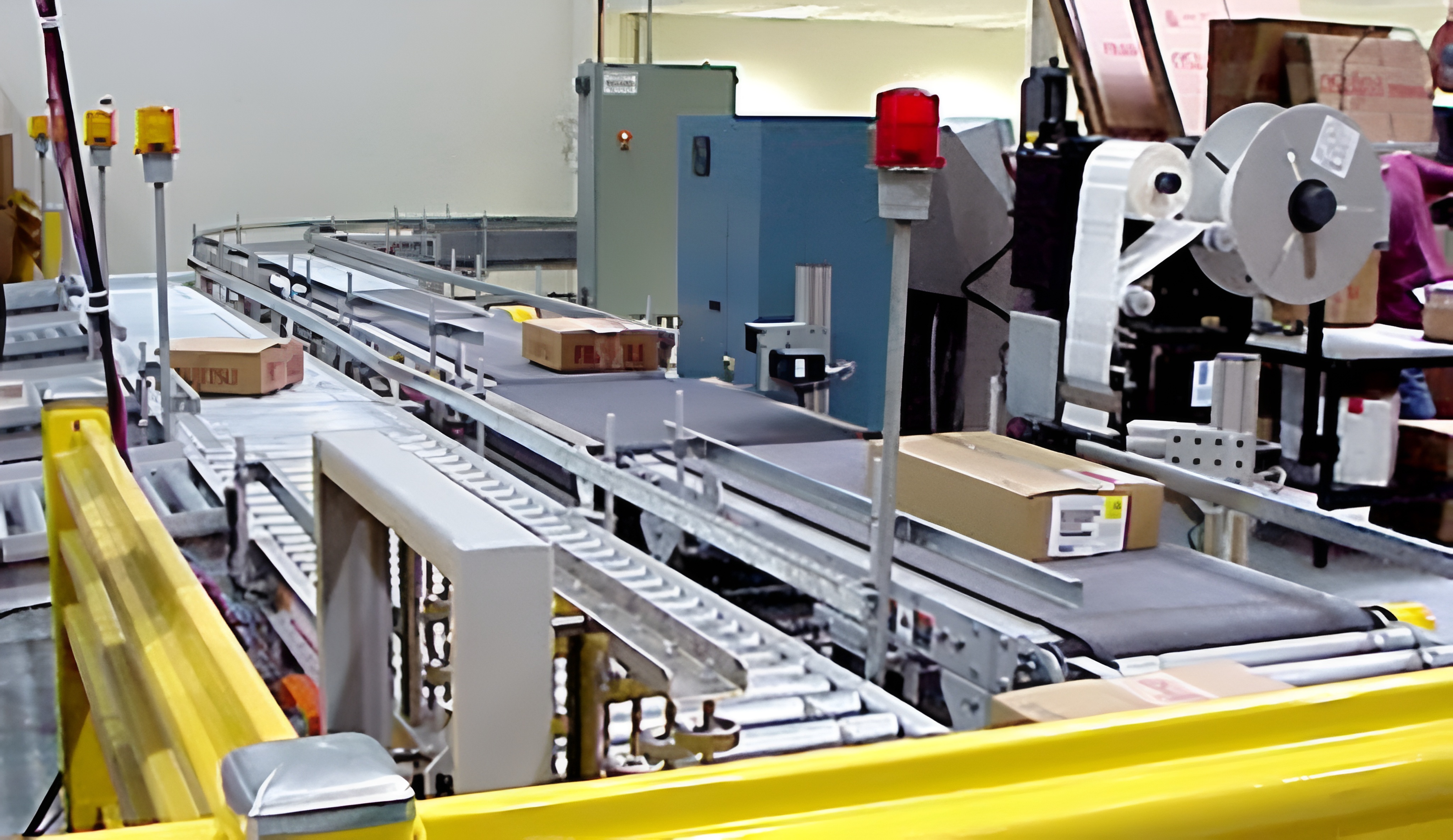
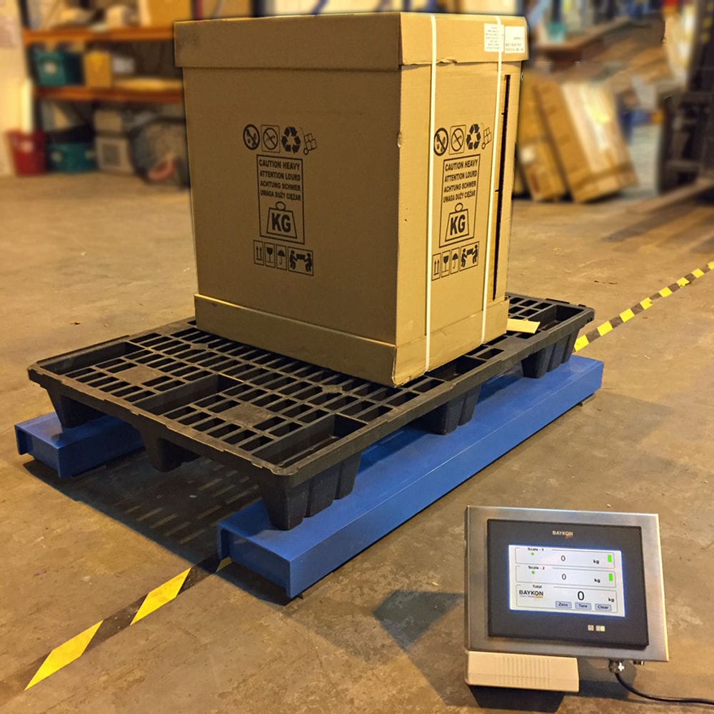


Powder batching system consists of industrial control computer, control software, system power supply and distribution and on-site inspection and control. Computer constitutes the center of control and management, can operate in general industrial environment, the field of primary signal after conversion, amplification into a standard 4 ~ 20mA signal to OPTO22RTUMUX control machine, the weighing module to send industrial control machine to collect data, scale conversion, filtering and processing with the given value sent to the PID function block operation, respectively, sent two ways to regulate the value of the output of the D / A conversion, all the way! Adjust the frequency converter speed of feeding screw to control the feeding quantity, and adjust the opening degree of electric regulating valve to control the flow of materials, so as to achieve the purpose of feeding materials accurately according to the proportion.


 020-34563445
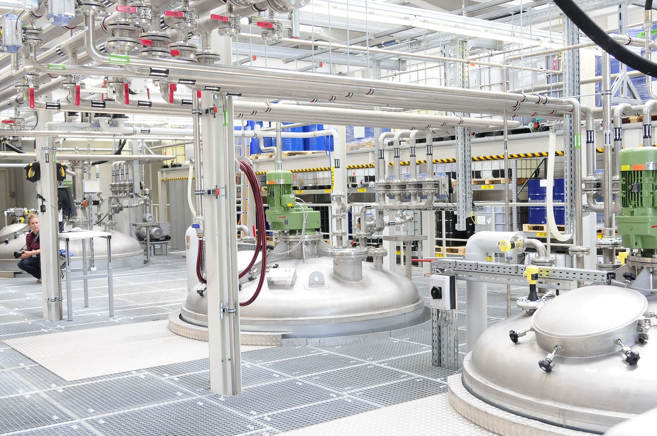
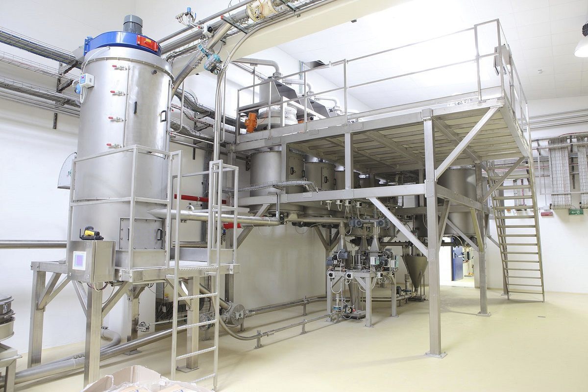
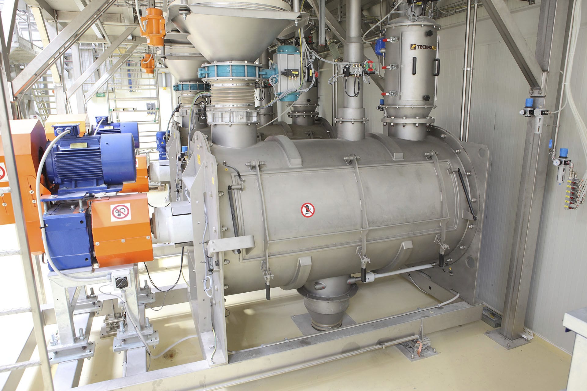
The metering feeding system includes feeding stations, feeding devices, batching warehouses, etc. It determines raw and auxiliary materials according to the process formula and identifies the raw and auxiliary materials; The main raw materials are directly fed into the storage bin through the dust-free feeding station according to the required varieties and quantities in the operation plan, and then moved to the batching station through the elevator, or the raw materials are fed into the dust-free feeding station and sent to the fixed Weighing system at the batching station through the vacuum conveyor. The feeding system is mainly composed of a pneumatic conveying negative pressure suction fan and a suction type pneumatic conveying equipment device system. With a unique wear-resistant component structure and material, the service life of the suction fan is extended. The vacuum negative pressure generated by the high-pressure fan is used as the conveying power to suck the material into the conveying pipeline. The material gas is separated by a material gas separator, and then the separated material is discharged into the receiving bin by an electric lock valve under the action of gravity. The equipment operates safely to reduce the occurrence of safety accidents and lower the operating costs of the enterprise. The system enables materials to be quickly and uniformly mixed under the action of airflow, avoiding the wear, dust, and energy consumption problems caused by mechanical stirring in traditional mixing equipment. The automatic mixer introduces airflow into the mixing chamber through compressed air or other gases. The airflow forms a high-speed rotating gas-solid two-phase flow in the mixing chamber, generating strong aerodynamic forces. The powdered or granular materials to be mixed are fed into the mixing chamber through the feeding port. The material forms a suspended state under the action of the airflow and is drawn into the airflow. The kinetic energy and fluid dynamics effects of the airflow keep the material suspended in the mixing chamber, constantly circulating upwards, downwards, or in the airflow. The speed and direction of the airflow can be adjusted to control the suspension state of the material. Under the action of airflow, collisions, friction, and diffusion occur between materials, thereby achieving uniform mixing of materials. The material continuously rises, falls, and circulates in the airflow, allowing different particles to mix with each other and achieve a uniform mixing effect. The mixed materials form a uniform suspension state in the mixing chamber and are discharged from the mixing chamber through the discharge port.
The weighing hopper machine adopts a weighing frame with a self-propelled device. A discharge funnel is installed on the weighing frame, and a hopper door is set at the lower part of one side of the discharge funnel. A measuring Feeder is installed at the bottom of the discharge drain. The measuring feeder is fixed by a hanging bracket. The output end of the measuring feeder is equipped with a hopper scale, and the bottom of the hopper scale is equipped with a discharge hopper door that controls its switch. The bottom of the hopper scale is equipped with a discharge hopper, and the discharge hopper is equipped with a screw conveyor; The hopper scale and the discharge hopper are both installed on the gantry, located on one side of the weighing frame and connected to the supporting gantry through a connecting device. The hopper scale is equipped with a weighing module; Standard weights are installed on both ends of the hopper scale through connectors; The structure of the feeding hopper door is equipped with bases at both ends, and cylinders are installed on the bases through fasteners; A pair of bucket doors are symmetrically installed at the bottom of the hopper scale, and a fifth lifting ear is set at the end of the bucket door. The head of the piston rod of the cylinder is fixedly connected to the fifth lifting ear through bolts; The structure of the connecting device is to install lifting ears and connect them through a pin shaft. It also uses an electric control room, which adopts a hopper scale control system and a computer data management system. The measuring and batching machine adopts a screw conveyor, which adopts a feeding port and a discharging port. The feeding port and discharging port are parallel to each other with a screw conveying mechanism. The screw conveying mechanism adopts a reducer, a conveying chamber, a screw, and a screw blade. The screw is located in the conveying chamber and one end is connected to the reducer for transmission, while the other end runs through and is connected to the discharging port for transmission. The screw blade is fixed on the screw. The diameter of the conveying chamber of the screw conveying mechanism is different, and it can be divided into a large screw conveying mechanism and a small screw conveying mechanism. The ratio of the diameter of the conveying chamber between the small screw conveying mechanism and the large screw conveying mechanism ranges from 1:2 to 2:3, and the ratio of the diameter of the spiral blades between the small screw conveying mechanism and the large screw conveying mechanism is the same as the ratio of the diameter of the conveying chamber between the small screw conveying mechanism and the large screw conveying mechanism. The weighing and batching machine combines screw conveyors of different diameters together. During normal conveying, the large and small screw conveying mechanisms can synchronize and quickly transport, effectively ensuring the conveying speed. When precise quantitative conveying is required, in the early stage of conveying, both the large screw conveying mechanism and the small screw conveying mechanism can be turned on simultaneously to quickly convey materials. When the material is about to reach the conveying capacity, close the large screw conveyor mechanism, and slowly transport the small screw conveyor mechanism until it reaches the conveying capacity and stops the small screw conveyor mechanism. During this process, due to the closure of the large spiral conveying mechanism and the limitation of the diameter of the conveying chamber 6, large pieces of material can only be conveyed by the large spiral conveying mechanism. When the large spiral conveying mechanism pauses in advance, even if the large pieces of material slide off the end face of the conveying chamber, it will not affect the final quantitative conveying accuracy.