


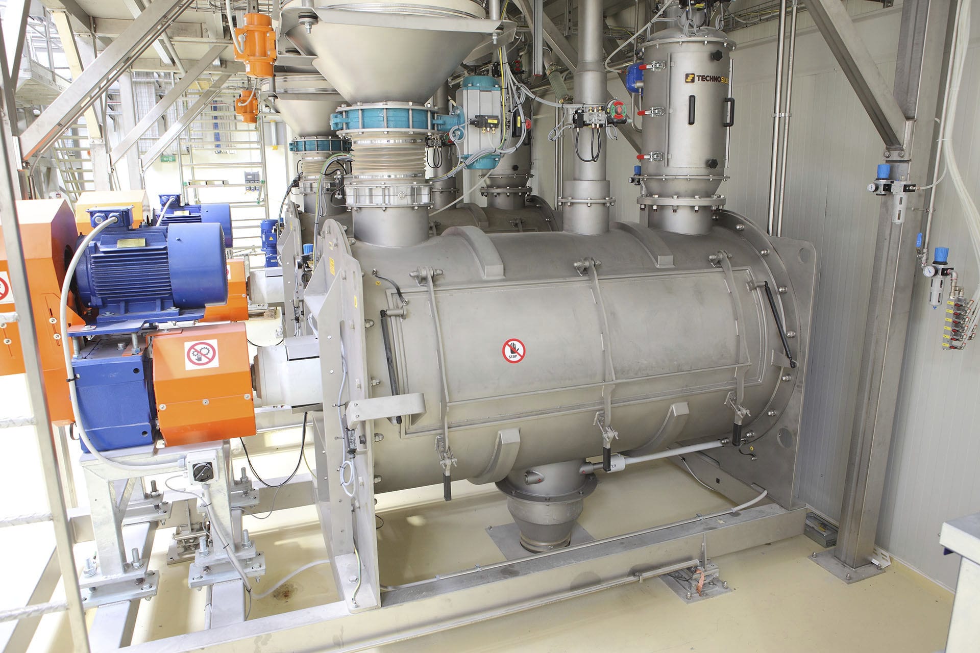


Mixing Weighing dosing system based on PC and precise quantitative dosing is a set of machine, electricity, signal processing and dosing in one of the technical equipment, electrical part is mainly composed of weighing sensor, weighing instrument, programmable controller (PLC), frequency converter, industrial computer and printer. In the process of dynamic weighing, the weight signal of the weight sensor on the quantitative weighing hopper is received. When the weight of the material in the hopper reaches each set value, the output I/O quantitative signal to the PLC. PLC collects the quantitative output signal of the weighing display instrument, and controls the output frequency of each frequency converter through PLC, so as to control the thickness and fine feeding amount of the corresponding vibration feeder and the switching door action of each weighing hopper.

 020-34563445
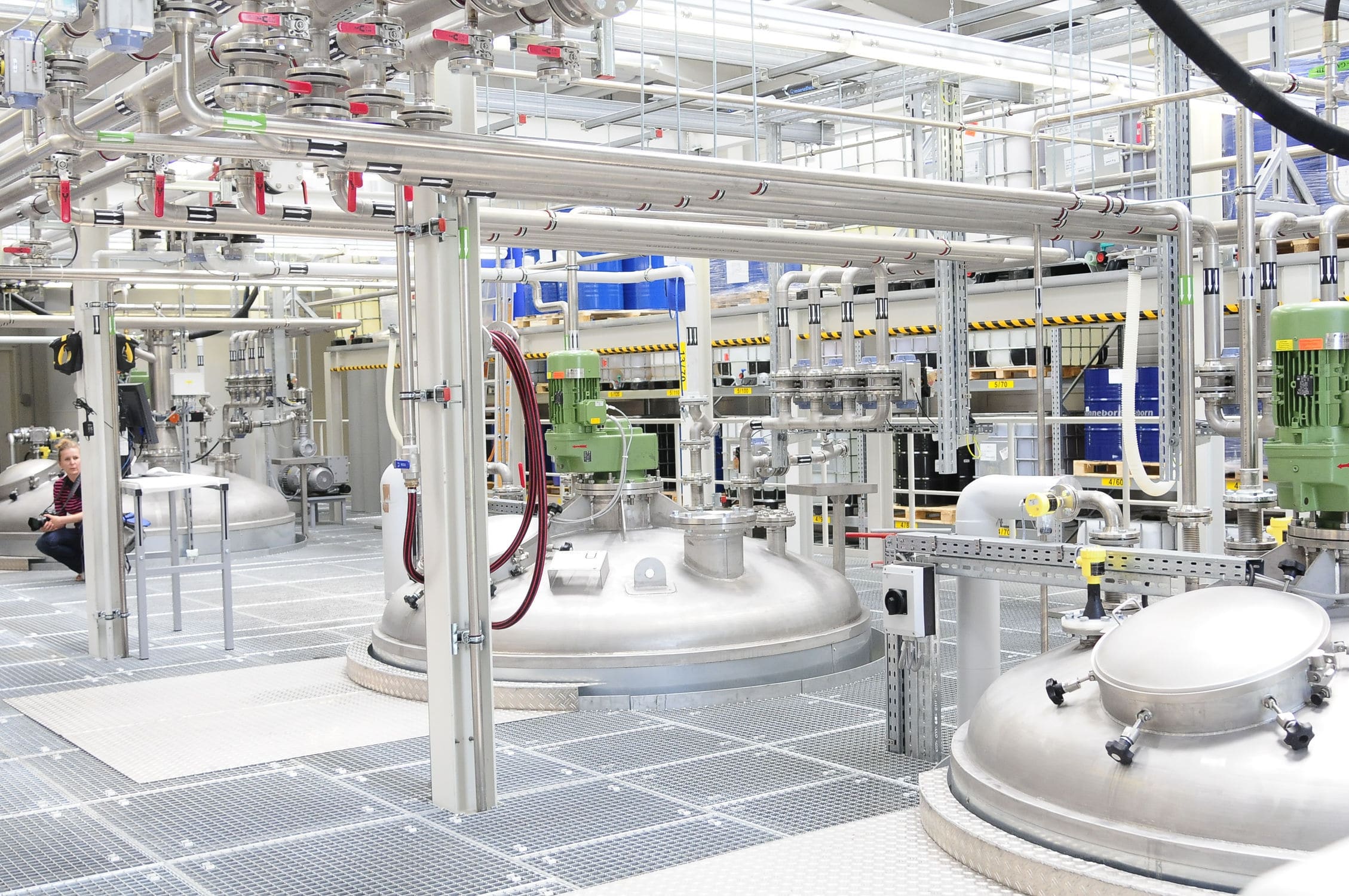
The mixed weighing Batching system is an automatic batching equipment applied in industrial production. The computer with the material feeding coordination calculation program serves as the control center, conducting automatic control for the mixing process at the production front to achieve the goal of machine replacement of human labor. It not only has high measurement accuracy and automatic control features, but also can save a large amount of production labor for enterprises, bringing huge benefits to them.
The weighing of the reaction vessel adopts a floating and semi-floating combination, enabling the subsequent formed weighing control system to automatically measure and weigh the data, store it in the computer and manage the weighing data. It is achieved through the change of heat transfer by the jacket, and realized by controlling the electric heating power. Temperature control must detect the temperature of the reaction vessel and the jacket, and the control program automatically controls the temperature based on the changes in temperature inside the jacket and the reaction vessel. The feeding system will start from the raw material feeding pump and deliver the qualified materials to the reaction vessel. It will include the control of all input and output valves, interlocks, the start and stop of each material feeding pump, the control status detection of fast and slow feeding, and all data processing functions.
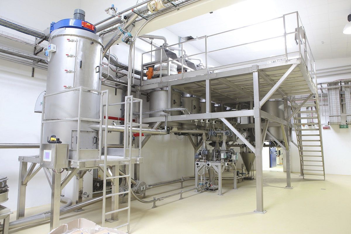
The feeding system mainly uses PLC, touch screen, and weighing module control. The PLC and its corresponding electrical control main circuit are installed in the electrical control cabinet to control the on-site signals. The control cabinet surface is installed with a touch screen HMI for monitoring and adjustment, displaying the working status of batching, time settings, batching adjustment parameters, alarm information, etc., to improve the reliability of the safe operation of batching. The new materials obtained by mixing different types of powdery substances in different weight ratios are realized through dynamic data exchange (DDE) technology for data collection and transmission from the production site, completing data interaction between VB and InTouch, and providing a specific configuration process for the batching scheme.
Equipment form: Horizontal, vertical multi-layer/single-layer/insulation
Equipment series: 50L - 150M3
Working temperature: Normal temperature / In-situ sterilization
Working pressure: Normal pressure
Heating and cooling methods: Vacuum, electric heater, jacket and internal spiral tube, sterile air
Mixing method: Shaft, drum type,
Control form: Automatic weighing batching control (manual control)
Material: High-quality stainless steel
Temperature control range: 20 - 60℃, ±0.5℃
Speed control range: 0 - 30rmp, ±1%


