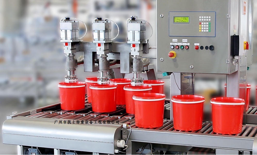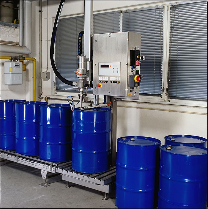




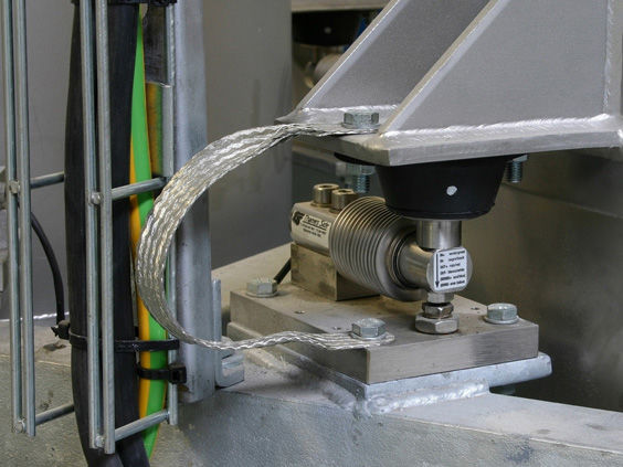
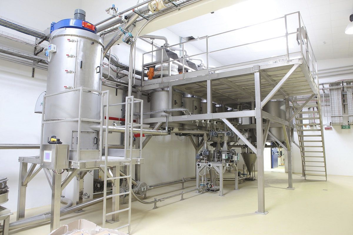
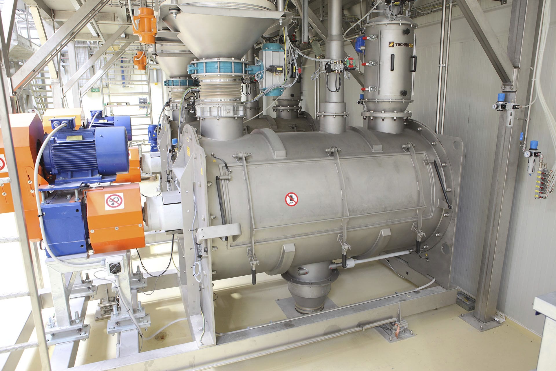
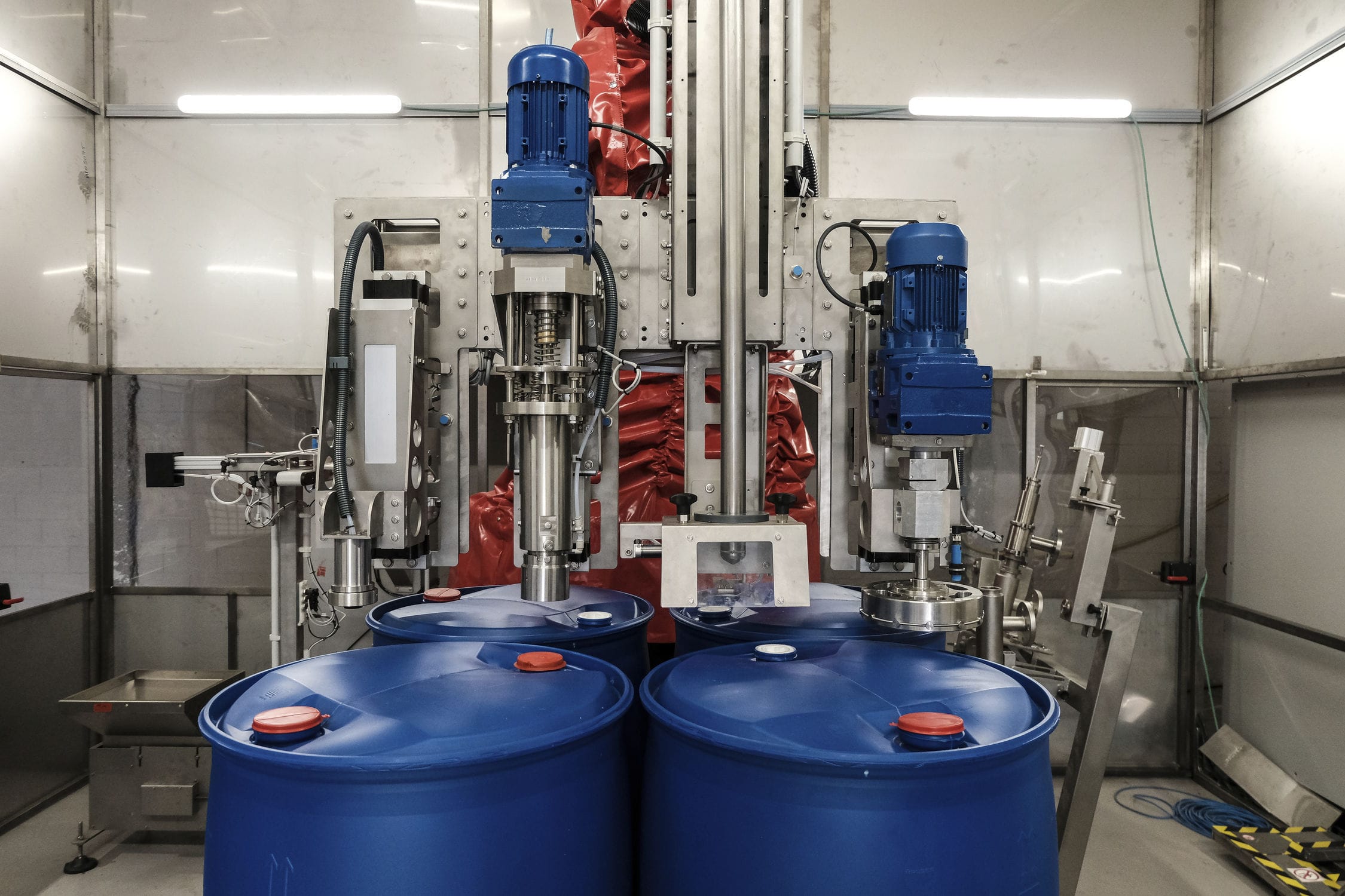
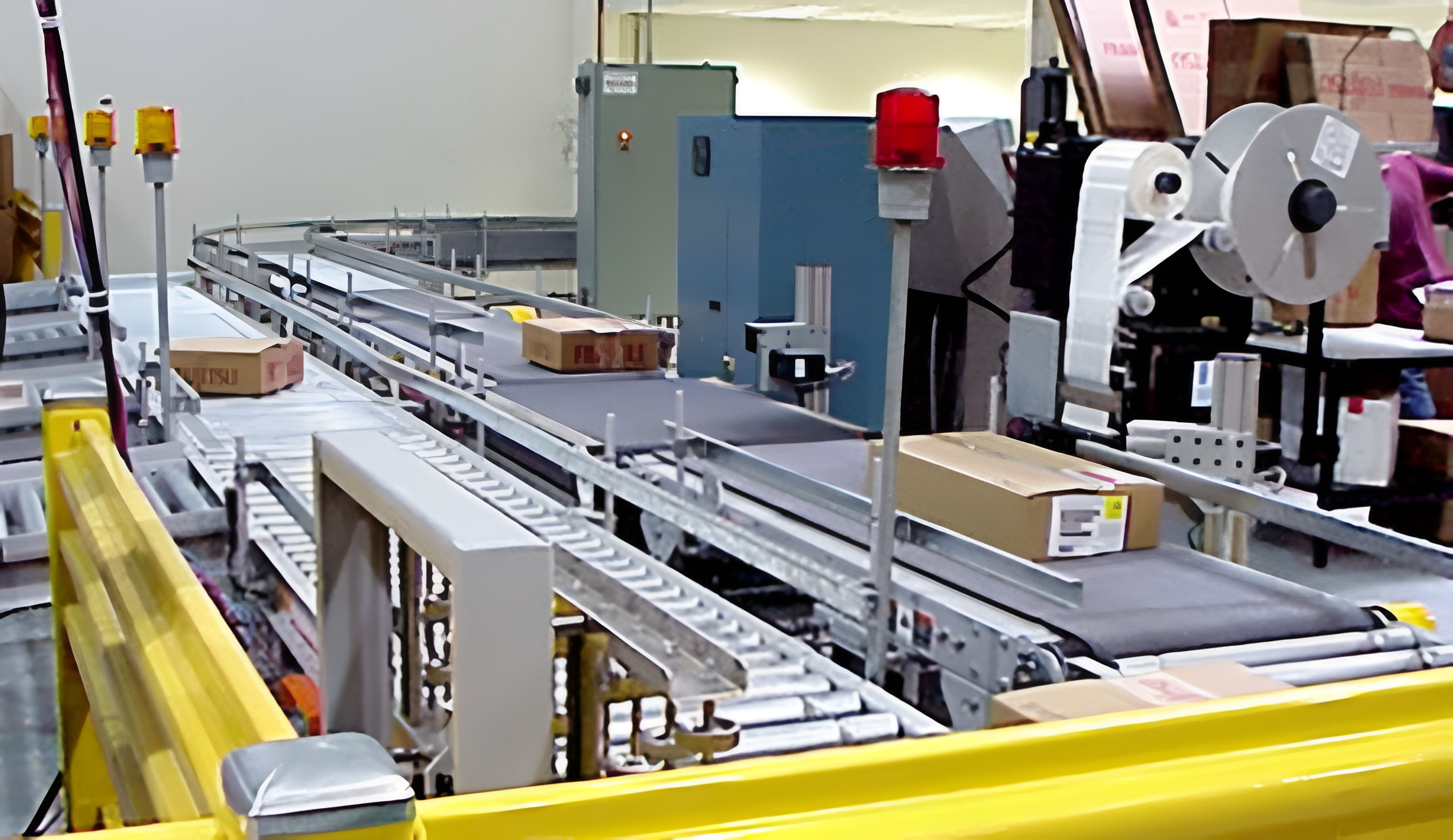
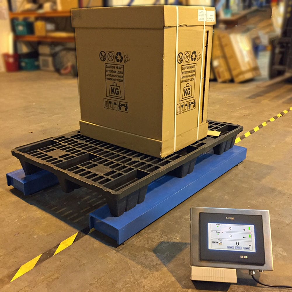


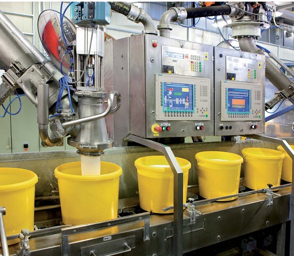
The Weighing automatic filling machine is an embedded industrial control and data acquisition weighing system, which is collected by an external weighing module and stored in an embedded database through a data processing program. The application program can obtain and update the status of each control point in real time through the processing of the database records, and issue commands to achieve the purpose of real-time monitoring and control.

 020-34563445
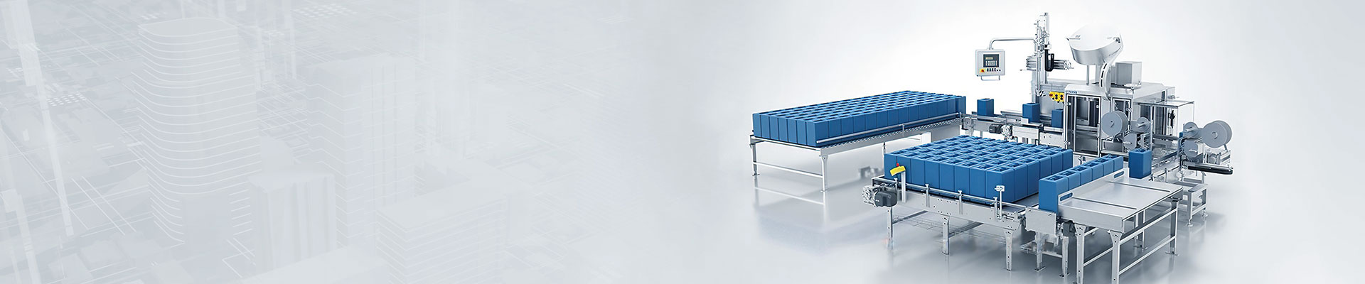
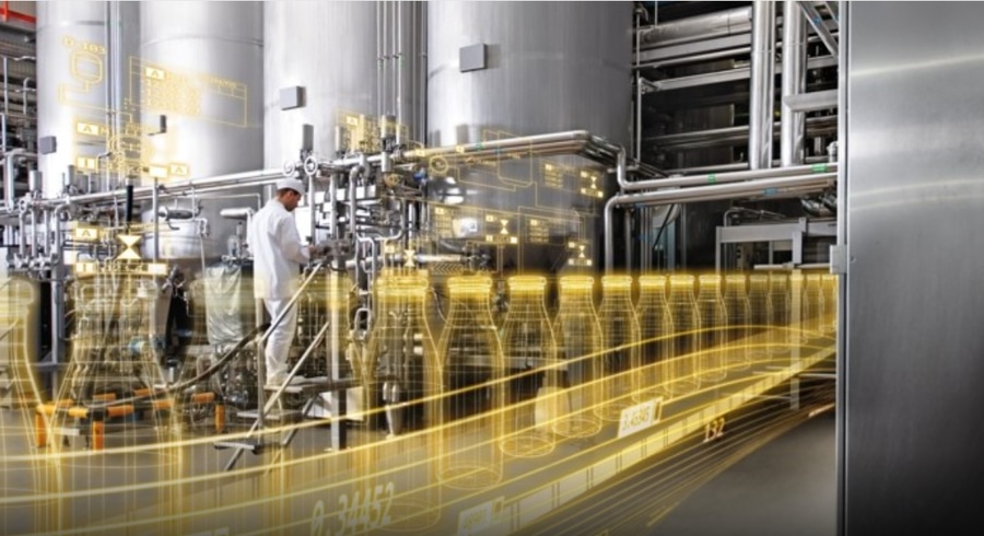
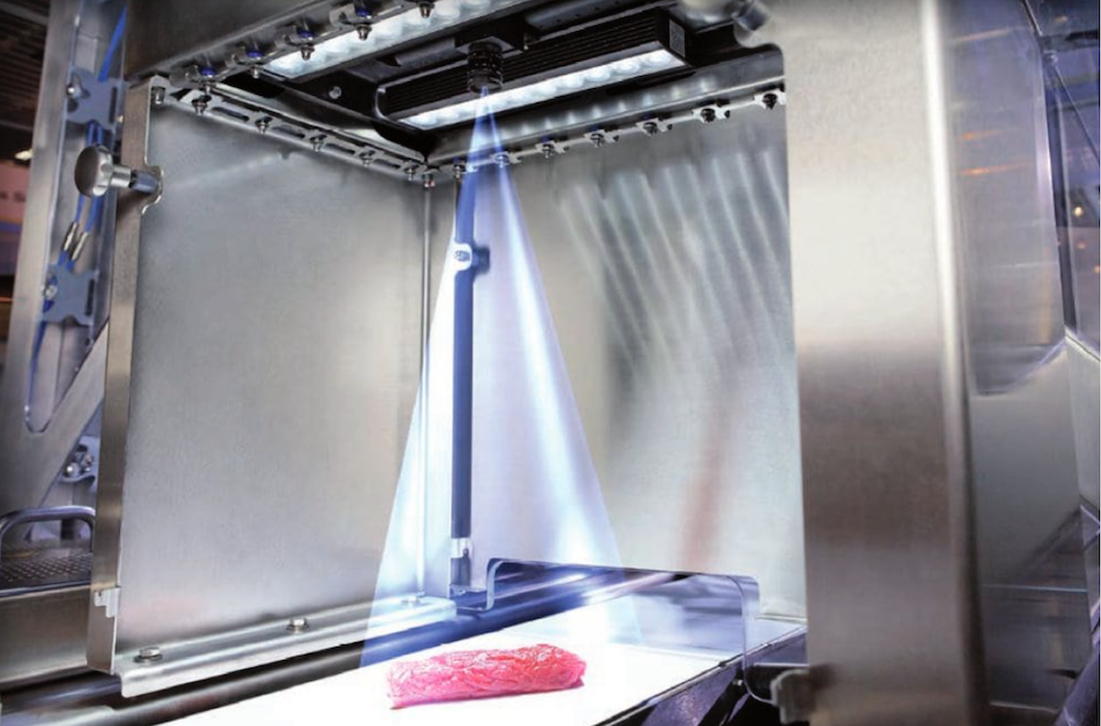
After the metering automatic Filling machine sends the information of reading the weighing data through the serial port to the Weighing system, the weighing system, upon receiving such information, will send data through the RS232 serial port to the serial port of the single-chip microcomputer. The calibration of the automatic filling machine (capacity-controlled and weight-controlled) can be completed through the weighing method. It is developed based on the VB platform with a serial port (RS232) and includes functions such as data acquisition, data processing, file generation, and data printing. The automatic filling machine, on the basis of rapid and accurate distribution, uses a frequency converter to adjust the speed of the pumping unit according to the viscosity. It adopts a distributed transmission method based on the mechanical hand, "one machine, one independent pipeline", to make the system more flexible. This weighing system also has functions such as consumption statistics, cost analysis, and quality tracking. The automatic filling machine realizes functions such as cleaning, filling, sealing, cap-laying, packaging, and detection through automatic control and manual control, forming a rapid integrated automatic Filling system. Additionally, to ensure that the system can be well resolved in case of unexpected failures, the system is equipped with emergency stop switches, etc. For the non-conforming products detected, they are removed by the mechanical hand. And the entire automatic filling system is monitored in real time using the Groupware software, which can better understand and modify the production process and control program.
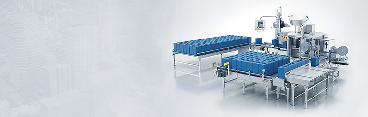
The automatic Liquid filling machine is composed of a stepper motor, a filling head, a gear pump, a conveyor belt and an electrical control box. The electrical part mainly includes the stepper motor and its driving power supply, a counter, an electromagnetic valve of the filling head, a frequency converter of the gear pump, a conveying motor and the corresponding control circuits. The automatic filling machine includes a frame. On the frame, there are two sets of independent filling mechanisms. Compressed air is controlled by an air valve to make the piston in the cylinder move up and down. The up and down movement of the piston is made by the pull rod to make the mouth plug move up and down. Through the pull rod, the mouth plug moves up and down, and the opening and closing of the outlet are realized inside the liquid filling head. When the outlet of the liquid filling head is open, the liquid output by the volumetric metering is controlled by a pipeline to the inlet of the liquid filling head, and then through the body of the liquid filling head, it is filled into the container from the outlet. When the outlet is closed, even if the liquid has a high pressure, the body cannot flow out. The filling mechanism includes a storage hopper and an outflow mechanism. Below the storage hopper, there is a rotating disc driven by a drive motor. On the rotating disc, there are several holes corresponding to the outlet end of the storage hopper. Below the rotating disc and at the corresponding position of the holes, there is a storage metering cylinder. Below the storage metering cylinder, there is a fixed base plate. On the fixed base plate, there is an outflow port corresponding to the storage metering cylinder. Above the rotating disc and at the corresponding position of the outflow port, there is a discharging mechanism. The outflow ports of the two sets of filling mechanisms are on the same horizontal line, integrating the two sets of filling mechanisms together, so that their outflow ports are on the same horizontal line, thus cooperating with the existing fully automatic bag-making machine to form a continuous fully automated production line mode. Compared with the existing semi-automatic filling method, it greatly improves the production efficiency.
When the main shaft of the gear pump rotates once, the volume of the liquid discharged is an accurate fixed value. At the same time, the liquid discharge volume increases uniformly as the number of engaged teeth on the gears increases. Even the liquid volume discharged from the start of the meshing of a pair of gears to the separation process can be approximately regarded as being discharged uniformly. Its function is to convert pulse electrical signals into corresponding angular displacements. If a pulse electrical signal is given, the stepper motor will rotate a fixed angle corresponding to it. The angular displacement of the stepper motor is in a direct proportion to the number of pulses, and the rotational speed of the stepper motor is also in a direct proportion to the pulse frequency. Within the load capacity range, the above proportion relationship will not change with the size of the power supply voltage and environmental conditions fluctuations, and it can achieve stepless speed regulation within a wide range by changing the pulse frequency. At the same time, it can start quickly, reverse, brake and stop under the control of electrical pulses. One electrical pulse can correspond to a very small angular displacement, and it is accurate, uniform, has high step accuracy, no skipping or skipping, has a large output power, and can directly drive the load. Through the speed-changing and deceleration device, the output shaft of the stepper motor is connected to the driving shaft of the gear pump. The stepper motor can be used as the power source for filling liquid, and by controlling the number of steps of the stepper motor, the rotational speed of the gear pump can be precisely controlled, thereby achieving the purpose of precise measurement.
The filling system lifts the filling valve's hydraulic rod by the cylinder, causing the filling valve opening to fully release the material. At this time, the Electronic scale is in a lower position due to its own gravity, creating a pulling state for the electronic scale. A large-flow filling process is carried out. When the filling reaches approximately 95% of the total capacity, due to the combined effect of the material weight and the pre-filled filling gun, the metering filling gun is lifted for the first time. The signal is interrupted to the electromagnetic valve, and the signal is input into the logic circuit, causing the first cylinder on the filling valve to act. The stroke valve rod moves down, and the stroke valve closes a large part. The micro-motion cylinder closes the pre-supporting force of the electronic scale, and the metering filling gun drops to the lowest position. When the small-flow filling reaches the measured weight, the filling gun is lifted again, and the signal is fed back to the logic control circuit again, opening the second cylinder on the filling valve to release the material. The valve rod falls under the action of the spring, and the filling valve opening automatically closes. One filling cycle is completed. When using a gear pump as the power for the outflow filling, when the filling valve is closed, the material can flow back from the upper outlet through the pipeline to the feed port of the gear pump, thus avoiding overpressure of the filling head.
The structure of the filling head of the automatic liquid filling machine is a double-stroke double-acting cylinder. The cylinder drives the valve rod inside the filling head to move up and down, thereby achieving the opening and closing of the filling head. The working process of the filling head. When the filling head opens the valve, the action is completed in one step. That is, under the lifting of the cylinder, the valve rod of the filling head moves upward along the entire designed stroke, and begins to perform high-flow rapid filling. When the filling head closes the valve, the action is completed in two steps. When the rapid filling reaches the coarse valve closing set value, under the push of the cylinder, the valve rod of the filling head first moves downward for a certain designed stroke, and begins to perform low-flow slow filling; after a period of time, when the slow filling reaches the fine valve closing set value, under the push of the cylinder, the valve rod of the filling head moves downward for another certain designed stroke. At this point, the filling head is completely closed, thus completing one filling operation. The structure of the filling head is a factor affecting the filling accuracy. The main factors are the sealing performance of the cylinder and the filling body, as well as the adjustment of the filling speed, especially the adjustment of the flow rate during slow filling. Maintenance personnel should inspect the filling head and adjust the filling speed and the on-off quantity of the valve to achieve the best value.