


The filling machine is equipped with different actuating mechanisms such as barrel feeding, liquid injection, stopper pressing and barrel discharging. To ensure the accuracy of filling, synchronous servo motors are used to directly drive the filling screw, and AC motors are selected to drive the barrel inlet and outlet conveying devices, filling turntables and stopper capping mechanisms. The entire filling system is composed of four units: on-site equipment components, signal acquisition components, command control components and condition monitoring components.

 020-34563445
The automatic weighing of liquid fillers by the weighing Filling machine consists of two steps: coarse weighing and fine weighing. First, the weight to be weighed is set. When the actuating cylinder carrying the filling gun moves accurately to the Electronic scale station on the material bucket under the control of the PLC, the filling gun descends, and the pneumatic valve fully opens. The liquid-like filler in the bucket begins to leak from the top of the weighing reaction vessel to the space below the pneumatic valve filling gun. There is an electronic scale conveyor platform installed below the space. When the weighing indication weight is 90% of the set weight, the pneumatic valve closes by 80% to complete the coarse weighing. The remaining 20% of the pneumatic valve continues to discharge the filler. When the value indicated by the electronic scale is consistent with the set value, the fine weighing is completed. The PLC will control the action of the pneumatic switch to close the pneumatic valve, and the weighing and packaging station operation is completed.
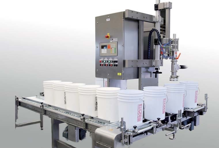
Below the weighing reaction vessel is the automatic filling machine section. There is one filling head. The bucket clamping device is driven downward by an air cylinder, and when it reaches the bottom position, it is clamped and positioned by another set of air cylinders. The lowering and clamping are controlled by position switches. After clamping and positioning, the filling head is driven downward by the third set of air cylinders, and when it reaches the position, the solenoid valve of the filling head opens, and the liquid filling begins. After a delay, the solenoid valve closes, and the filling capacity is controlled by controlling the opening time of the solenoid valve. The bucket discharging action process: the conveyor belt motor is controlled by a frequency converter to achieve stepless speed variation. After the motor starts for 1 second, the bucket insertion cylinder retracts, and the bucket insertion begins. 3 seconds later, the cylinder at the bucket discharge position extends to block the empty material bucket. A photoelectric switch is set at the bucket insertion position to detect the number of buckets. When the corresponding number is reached, the conveyor belt motor stops. The filling head descends to the bucket mouth, and the opening time of the filling head is controlled by the time input through the touch screen, which is controlled by the PLC. After the filling is completed, the filling head rises, the bucket clamping device relaxes and rises. The bucket discharge cylinder retracts, and the conveyor motor starts rotating again. 1 second later, the bucket insertion cylinder retracts, and the photoelectric switch starts detecting the number of buckets.
The Liquid filling machine is equipped with various actuators such as bucket feeding, liquid injection, plug pressing and bucket discharging. To ensure the accuracy of the filling process, synchronous servo motors are used to directly drive the filling screw, and AC motors are selected to drive the bucket inlet and outlet conveying devices, the filling rotating disk and the plug sealing mechanism. The entire Filling system consists of four units: on-site equipment components, signal acquisition components, command control components and status monitoring components. The servo system adopts the SIT series three-phase permanent magnet synchronous servo motor, with a wide speed ratio, constant torque output, 3 times overload capacity, a rated speed of 3000 rpm, and a pulse precision of 2500 p/r for the encoder feedback. The driving unit uses the latest digital signal processor DSP as the core, along with large-scale programmable gate array (CPLD) and MITSUBISHI intelligent power module (IPM), featuring high integration, small size, complete protection and good reliability, and a clear control process.
The rotational speed and angle of the screw are implemented based on the servo motor (that is, the angle of rotation of the servo motor). The speed and rotation angle of the motor are determined by the pulse signals output by the motor driver. The driver output is controlled by the PLC, and through the friendly human-machine interface (HMI) of the touch screen (mainly including setting of filling volume, adjustment of filling volume, speed setting, etc.), the instructions are sent to the PLC, thereby controlling the operation of the entire system.
The entire automatic filling machine consists of two parts: the main drive system and the screw filling system. The PLC system is used to control the servo motor of the screw, and a dedicated position control unit module is required. Each servo motor receives a pulse sequence from the position control unit to complete the screw advancement action. The main drive system involves the transmission of the filling tray, the plunger mechanism, and the track for entering and exiting the barrel. To achieve smooth speed adjustment, the inverter drives it. Based on the set parameters and the detected screw rotation speed, the error range of the filling volume is calculated. The speed of the servo motor controlling the filling screw is detected using an optical encoder, and the output pulse signal is sent to the high-speed counting module in the PLC position control unit for counting. Additionally, the PLC uses an RS-232C communication adapter to communicate with the industrial computer to set parameters and monitor the system.


