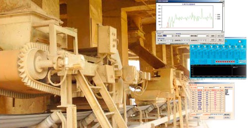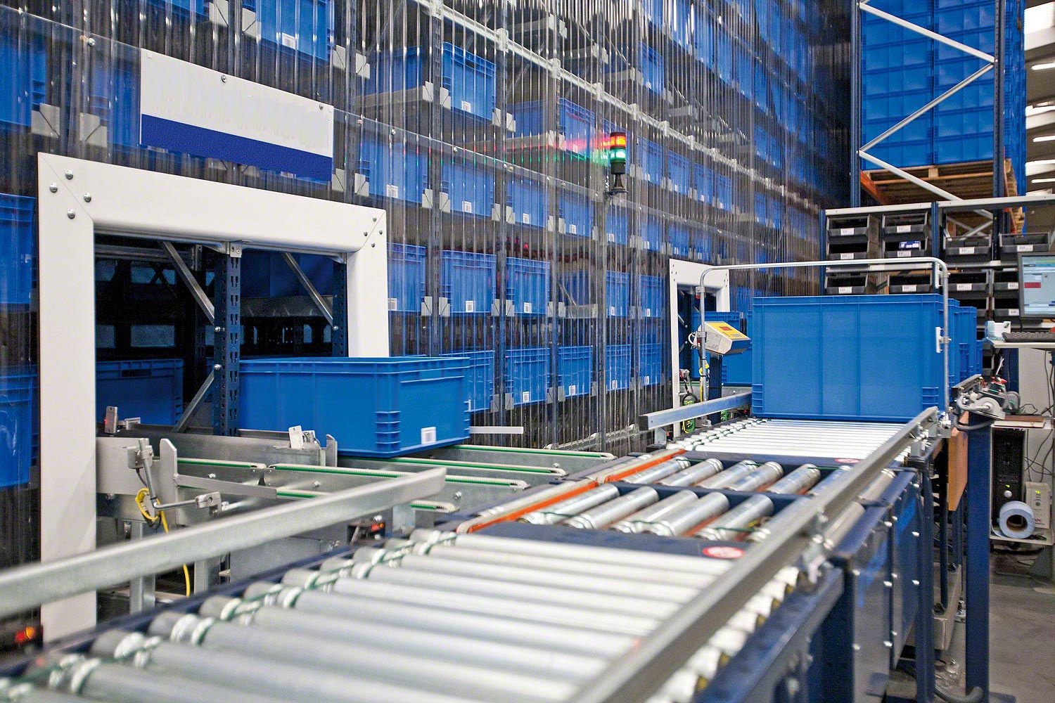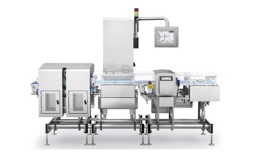









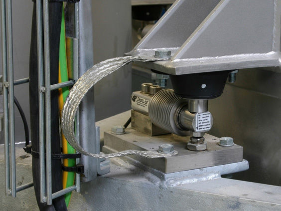
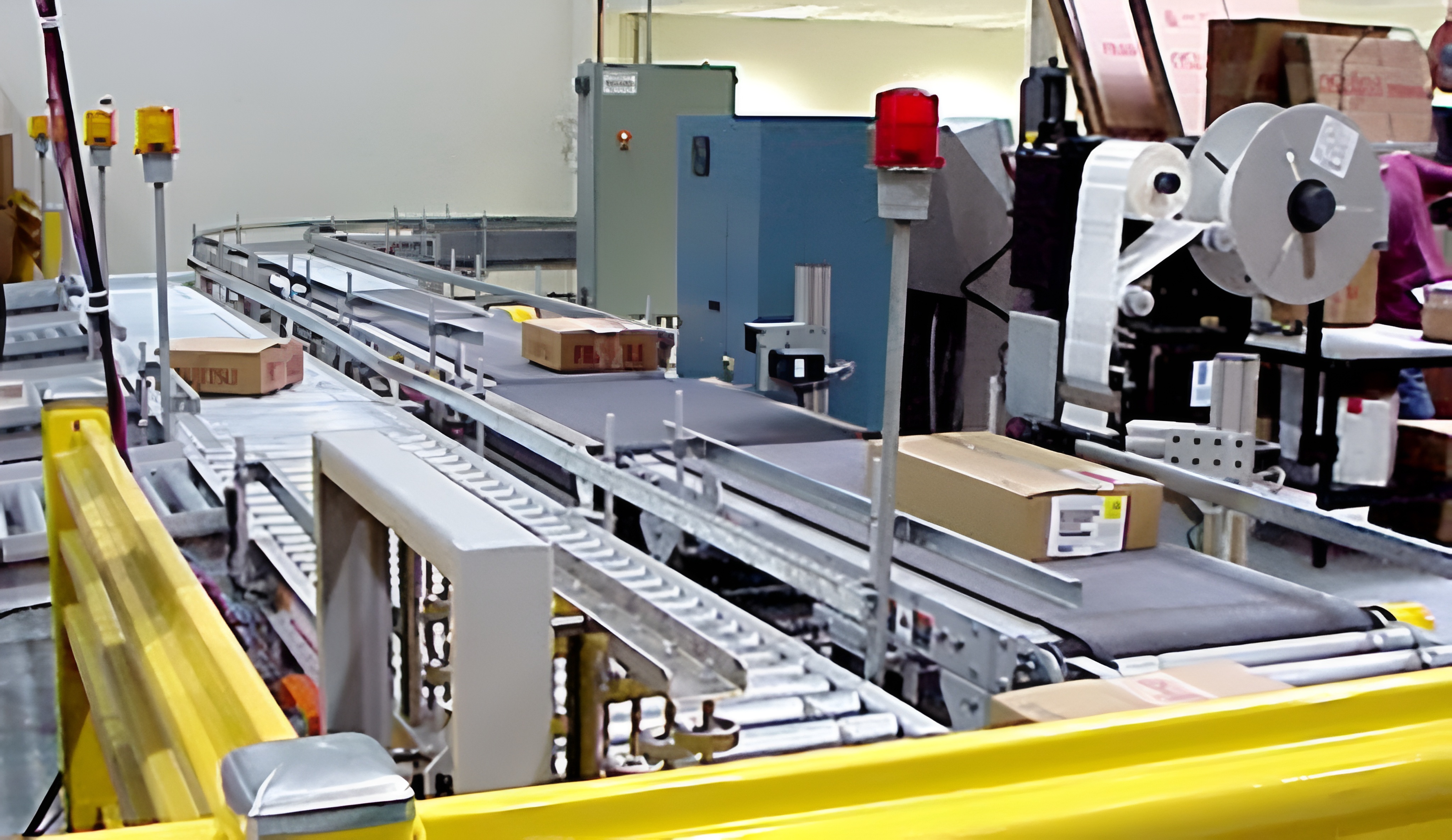
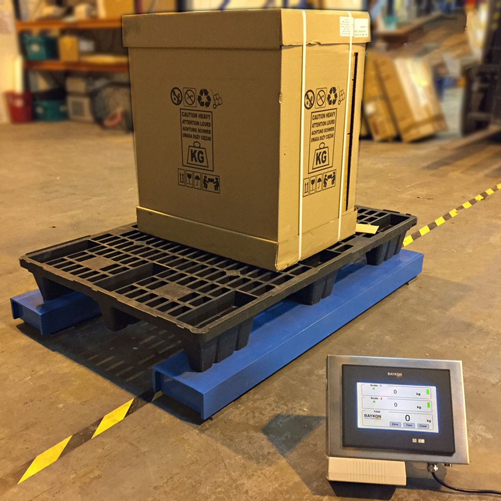


The Bridge Frame belt scale is equipped with a load weighing module bridge, mounted on the longitudinal beam of the conveyor. The weighing rollers on the weighing bridge detect the weight of the material on the belt and produce an electrical output signal proportional to the belt load. The speed sensor is directly coupled to the follower pulley or large diameter rollers and provides a series of pulses, each pulse representing a unit of belt motion, at a frequency proportional to the belt speed. The weighing instrument receives the output signals from the weighing module and the speed sensor, electronically multiplies the belt motion and belt load, and produces an instantaneous flow value and a cumulative total by calculating the time. The cumulative total and the instantaneous flow are converted into selected engineering units and displayed on the accumulator respectively.


 020-34563445
The bridge belt scale is equipped with a load weighing module on the bridge, installed on the longitudinal beam of the conveyor. The weighing roller on the weighing bridge detects the weight of the material on the belt and generates an electrical output signal proportional to the belt load. The speed sensor is directly connected to the driven drum or large-diameter roller, providing a series of pulses, each pulse representing a belt movement unit, and the frequency of the pulses is proportional to the belt speed. The weighing instrument receives output signals from the weighing module and speed sensor, multiplies the belt movement and belt load electronically, and generates an instantaneous flow rate value and cumulative total weight through time calculation. The cumulative total amount and instantaneous flow rate are converted into selected engineering units and displayed separately on the integrator.
There are four main types of belt scales: double bar multi roller, single roller, cantilever, and suspended. The conveyor measuring section of double bar multi roller and suspended scale frames is relatively long, generally consisting of 2-8 sets of rollers, with high measurement accuracy, suitable for places with large flow rates and high measurement accuracy requirements. The belt scale consists of a load-bearing device, a weighing module, a speed sensor, and a weighing instrument. The weighing bridge is installed on the conveyor frame. When the material passes through, the load-bearing device transfers the weight of the material on the belt to the weighing module. The sensor outputs a voltage mV signal proportional to the weight of the material, which is amplified by an amplifier and sent to an analog-to-digital converter to be converted into a digital quantity A, which is then sent to the arithmetic unit; After the material speed is input into the speed sensor, the speed sensor outputs a pulse number B and sends it to the arithmetic unit. The arithmetic unit calculates A and B to obtain the amount of material for this measurement cycle, and accumulates each measurement cycle to obtain the total amount of material continuously passing through the belt.
The instantaneous values of PLC are collected from the current or voltage signals output by the on-site belt scale. The instantaneous current/voltage values are collected by the analog module, calibrated by the lower level program calibration block, and converted into kilograms per hour. Then, they are converted into grams per second through the calculation module, and the cumulative amount of each batch is calculated by accumulation. According to the on-site signal configuration, the corresponding module channel configuration is used. The current type generally uses a 4-20mA signal, and the channel configuration Input Type is selected as 4-20mA. The flow data provided on site is voltage and current signals, which need to be converted into corresponding data before processing analog quantities. The value calculated by the metering module is the actual instantaneous value of the belt on site.
The weighing belt conveyor includes a lower chassis and a weighing frame. The top two ends of the lower chassis are fixedly connected to positioning screws, and are securely connected to the weighing frame through the positioning screws. A weighing module is provided at the distance between the lower chassis and the weighing frame. The inner bottom of the weighing frame is fixedly connected to a deceleration motor, and the output shaft end of the deceleration motor is fixedly connected to the main synchronous wheel. The upper end of the weighing frame is fixedly connected to a transmission shaft, and the outer part of the transmission shaft is sleeved with PU The conveyor belt is fixedly connected to one end of the drive shaft, which is driven by a slave synchronous wheel and a main synchronous wheel to the reduction motor. The two sides of the lower chassis are fixedly connected to adjustment support rods, and the top of the adjustment support rods is fixedly connected to a photoelectric sensor. The left side of the lower chassis is fixedly connected to an electrical control box, which is electrically connected to the weighing module, reduction motor, and photoelectric sensor. The top of the electrical control box is electrically connected to an audible and visual alarm.
The positioning screws of the weighing belt conveyor are distributed at the front and rear ends of the lower chassis, and are evenly distributed in a rectangular shape with the weighing module as the axis point. The transmission shaft is distributed at the front and rear ends of the weighing rack, and the PU conveyor belt wraps around the transmission shaft in a loop shape. The adjustment support rod and photoelectric sensor are located at the rear end of the lower chassis, and the bottom of the electrical control box is connected to the lower chassis using a clamping structure. The interior of the electric control box is equipped with a main controller, and the signal input terminal of the main controller is electrically connected to the signal output terminals of the weighing module and the photoelectric sensor through an A/D converter. The upper end of the electric control box is embedded with a weighing instrument, and the input terminal of the weighing instrument is electrically connected to the output terminal of the main controller, while the input terminal of the photoelectric sensor is electrically connected to the output terminal of the main controller.