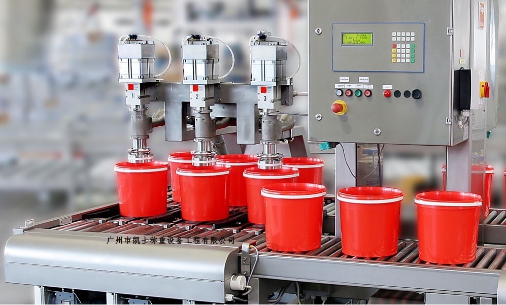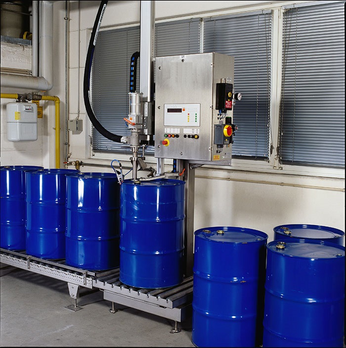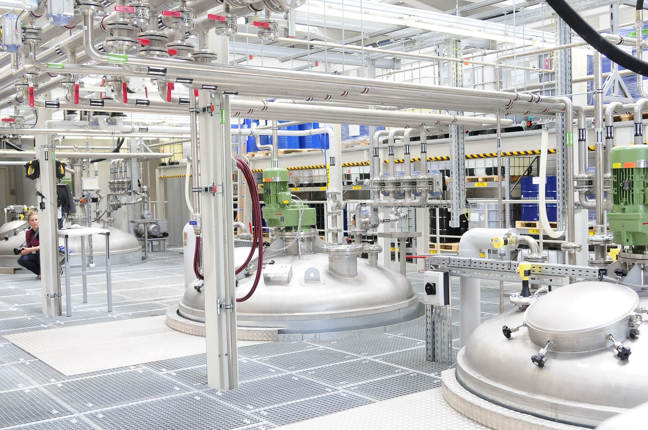


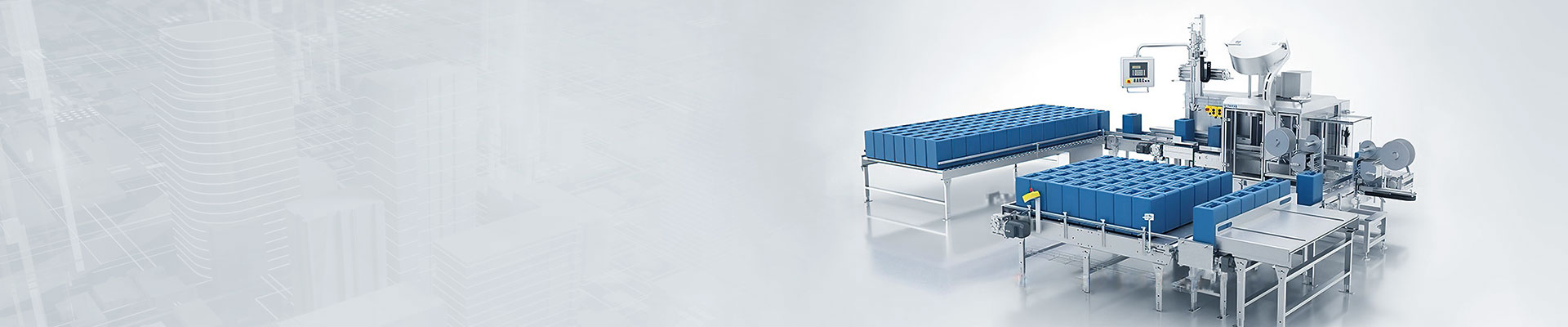
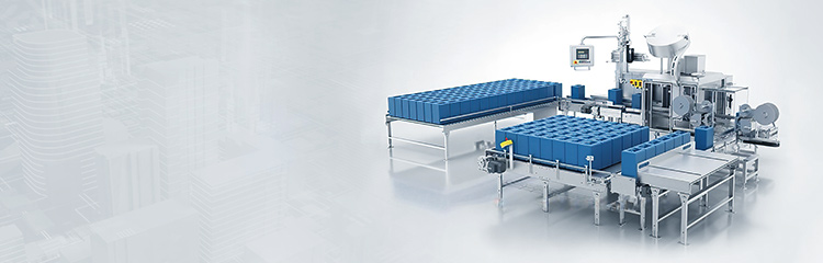


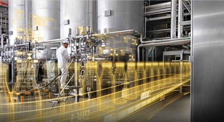
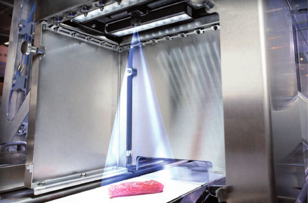
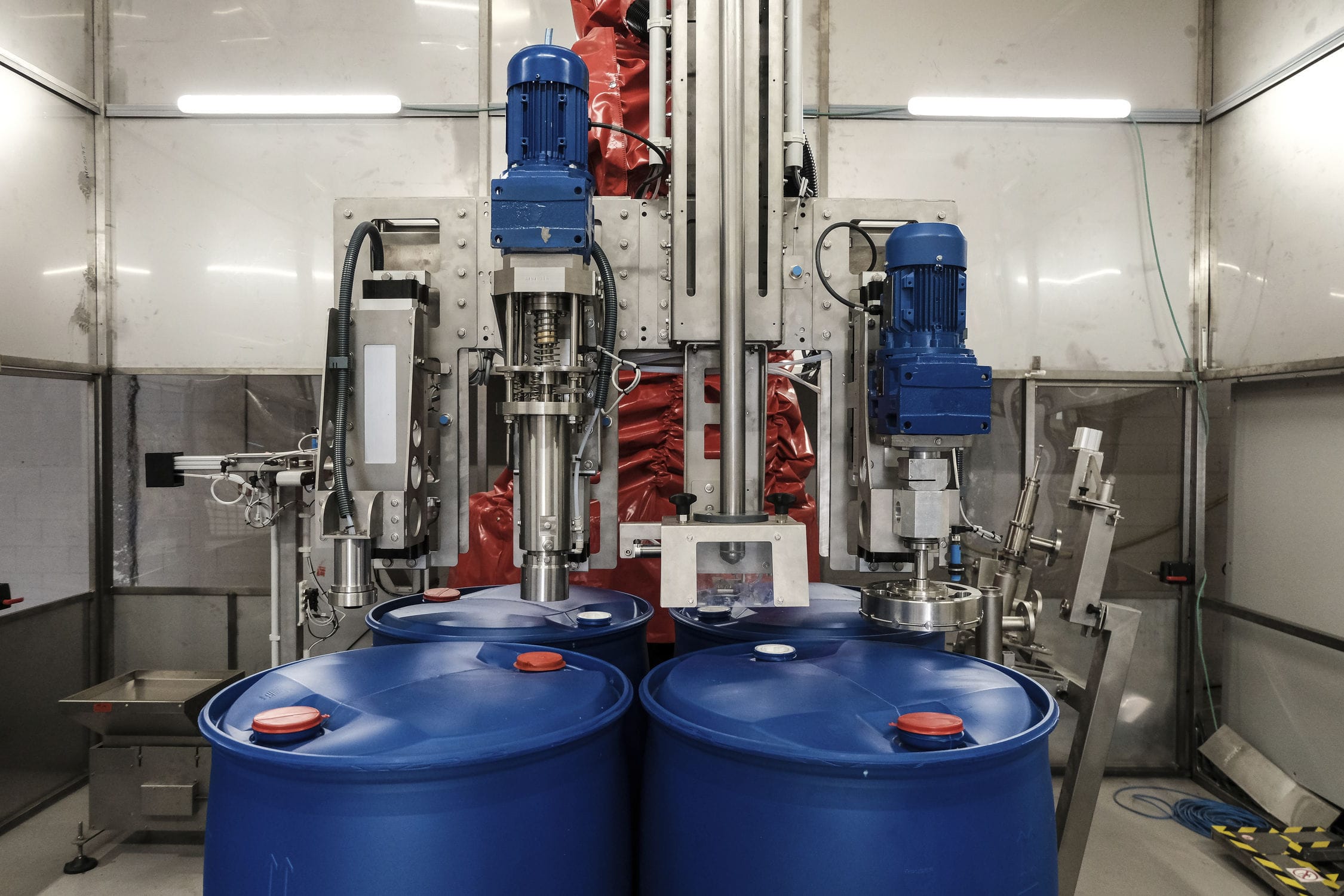


The main electrical control part of the filling machine is a Siemens S7300 series PLCCPU317-2PN/DP. The filling valve control part is a control system module EX484. Siemens PLC is responsible for the safety functions, speed control, high level buffer tank level control, return cycle heating, CIP in-situ cleaning, height adjustment, signal exchange, etc. The control system is composed of Siemens PLC buses. Siemens PLC control system consists of two buses, Profibus and ASI bus. The filling machine is responsible for filling valve metering cylinder level control, tank filling level control, filling valve pneumatic control, filling angle time control and so on. The filling valve control is composed of two buses: Powerlink bus and CANbus bus.


 020-34563445
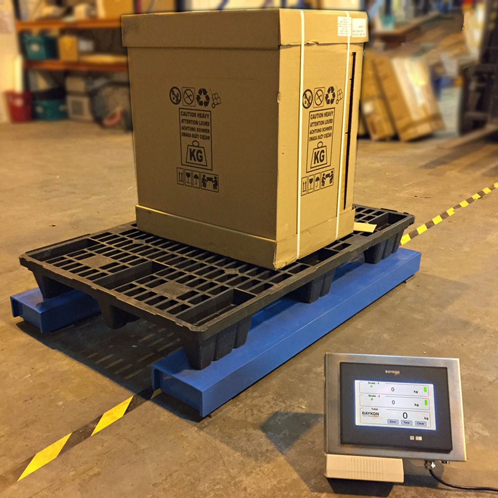
The operation mode of the Feeder is set to automatic operation. Turn on the switch and select "automatic" to drive the motor and the conveyor belt. When the weighing module detects that the bottle has reached the designated position and is in a stopped state, the conveyor belt stops running or the stop switch is activated to stop the conveyor belt. After the bottle is filled with liquid, the system automatically starts the motor, which drives again until it reaches another stop state and stops again. This action is repeated in a loop. A positioning switch is set on the Filling system. When the bottle reaches the designated position, the conveyor belt stops running, and the weighing Filling machine then starts filling work, which is completed within 5 seconds. During this period, if any abnormalities or errors occur, the system will issue an alarm signal in the form of sound and light. Equipped with weighing sensors and adders, used to detect the status of containers, and record the filled containers and the number of containers separately, counting from the start of system operation. The filling system reset and data reset are done manually to prevent data loss or system misoperation caused by automatic reset.
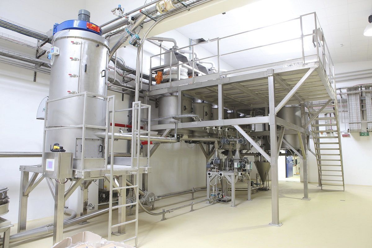
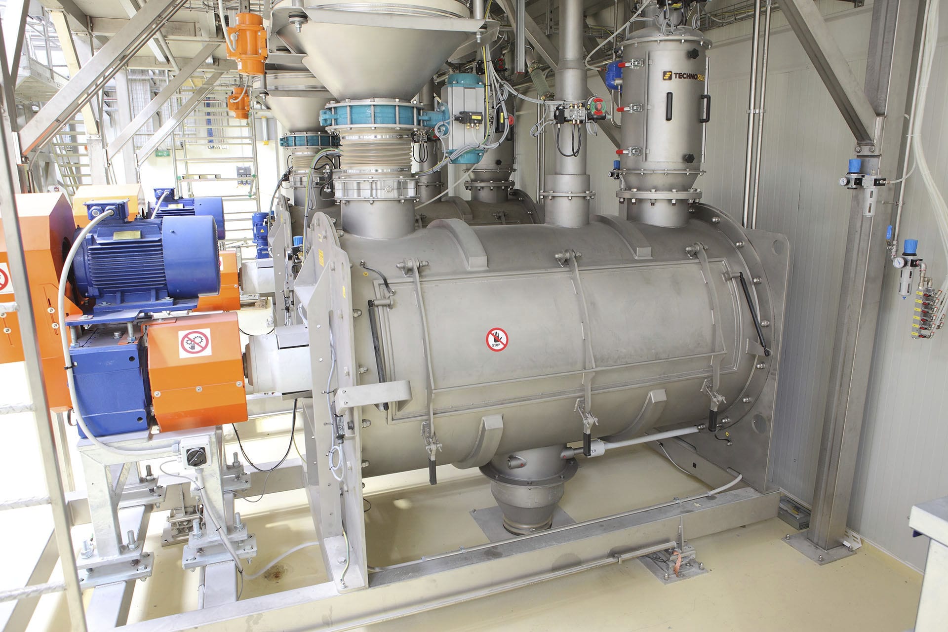
The weighing feeder includes a suction hopper, a storage hopper, a batching hopper, and a mixing hopper. The lower part of the suction hopper is connected to the storage hopper, and the discharge end of the storage hopper can be connected to the feeding end of at least one measuring screw. The discharge end of the measuring screw is connected to the feeding end of the batching hopper, and the lower part of the batching hopper is connected to the mixing hopper. The discharge end of the mixing hopper is connected to the feeding end of the batching machine, and the mixing hopper and batching machine are linked to stabilize the filling volume, thereby improving the longitudinal uniformity of the material. The measuring screw can accurately discharge the material. The measuring screw includes a motor, a machine base, a screw sleeve, and a conveying screw. A feeding port and a side connecting screw sleeve are set above the machine base, and the feeding port is connected to the screw sleeve. The motor is connected to the conveying screw, and the conveying screw passes through the screw sleeve. There is a feeding gap between the conveying screw and the screw sleeve. The motor is placed inside a motor compartment for dust prevention. The motor cover and motor are both connected to the motor base, which is connected to the side of the machine base. The motor is connected to the conveying screw through a coupling. The motor is a stepper motor, which improves the feeding accuracy. At least one set of measuring screws or one measuring valve is set between the storage hopper and the batching hopper for automation control. The measuring screws or valves are both set above the batching hopper, and the measuring valve is equipped with a cleaning port. The measuring screw or valve is set above the batching hopper. The measuring valve and measuring screw can be combined to achieve high batching accuracy.
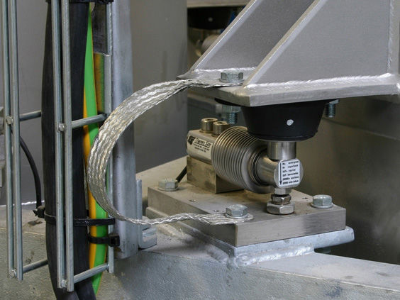
There are several storage hoppers evenly distributed along the circumference, which can achieve one-time proportioning of multiple materials. Each storage hopper is connected to a suction hopper, and the feeding method of one material, one hopper can ensure the unity of raw materials. Each storage hopper can be connected to the feeding end of the measuring screw or measuring valve. Multiple storage hoppers can be set according to user needs, and they are also equipped with measuring screws or measuring valves. The quantity is determined according to usage needs. The upper end of the batching hopper can be directly connected to the material. The middle of the batching hopper is movable and set in a support frame. A weighing module is set between the support frame and the outer wall of the batching hopper, which facilitates the overall weighing of each component of the material. The lower end of the batching hopper is inserted into the upper opening of the mixing hopper, and the lower end of the batching hopper is equipped with a pneumatic valve body (or solenoid valve), which opens after weighing. The upper opening of the mixing hopper is connected to the batching hopper through a pneumatic valve body, and the lower discharge port is flexibly inserted into the feeding port of the batching machine. A weighing module is installed between the bottom end of the mixing hopper and the frame. A mixing mechanism is installed on the side wall of the mixing hopper. The material ratio measurement range of the weighing module is 0.5% -100%, with an accuracy of 0.5%. The side wall of the mixing hopper is equipped with a mixing mechanism (mixing paddle), which can fully realize the mixing of materials. The bottom of the mixing hopper is equipped with a weighing module, which can realize the weighing and limiting of the mixed materials. The uniformly mixed materials directly enter the batching machine to ensure the uniformity of the raw materials. The Weighing system includes a control unit, and the suction feeder, measuring screw, and mixing hopper are respectively connected to the control unit for communication, facilitating the automation control of the equipment.
Technical parameters
Weight range: 10-20kg
Material interface: DN40 material
Import pressure: < 0.6MPa
Filling speed: 6-8 barrels (20L) per minute (with a diameter of 1.5 inches and a material flow rate of 20L/min)
Filling accuracy: 0.2 level spray gun structure, the materials in contact with the material are 316 and 316L stainless steel, and the materials in the remaining parts are 304 stainless steel, carbon steel, etc
Gas source used: pressure 0.5 ± 0.1Mp, consumption 10m3/h, quick connector 8mm air pipe
Power supply: 220 (-15%~+10%) VAC, 50Hz