

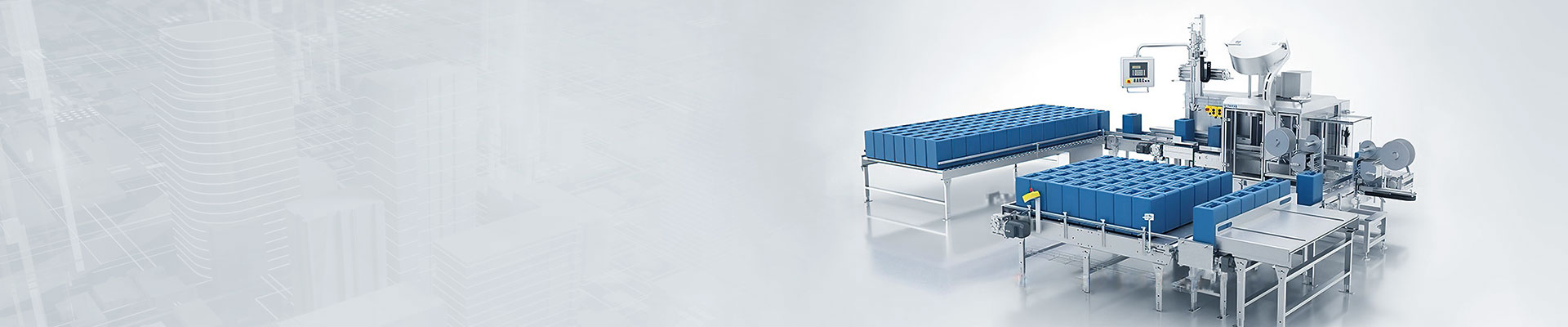


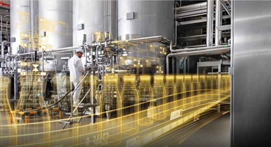


Reduction scales take the hopper scale and feeding mechanism as the whole scale body, through the weighing instrument or the upper computer constantly samples the weight signal of the scale body, calculates the ratio of weight change per unit of time as the instantaneous flow rate, and then through the processing of various software and hardware filtering technology, arrives at the "actual flow rate" which can be used as the control object.


 020-34563445
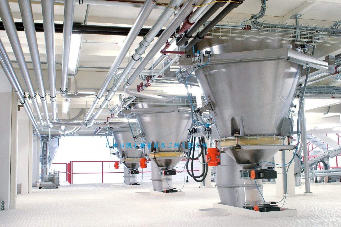
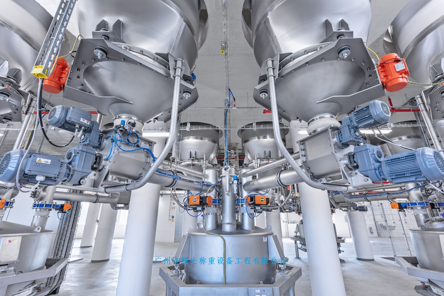
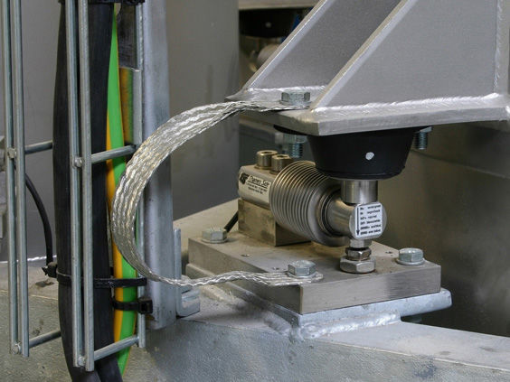
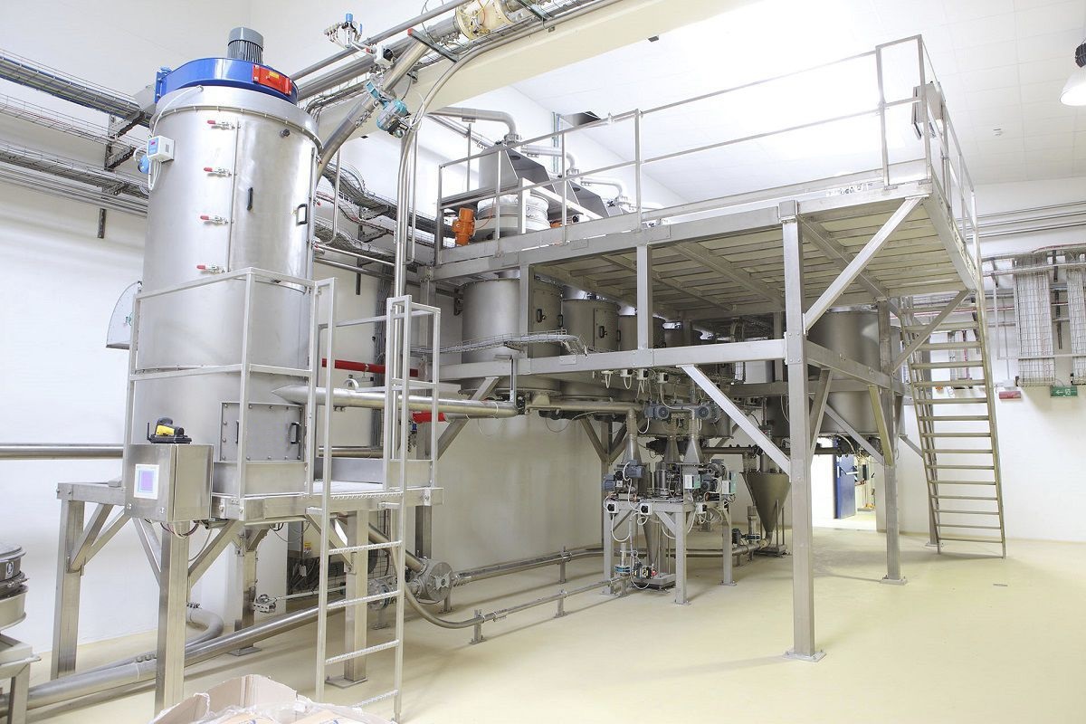
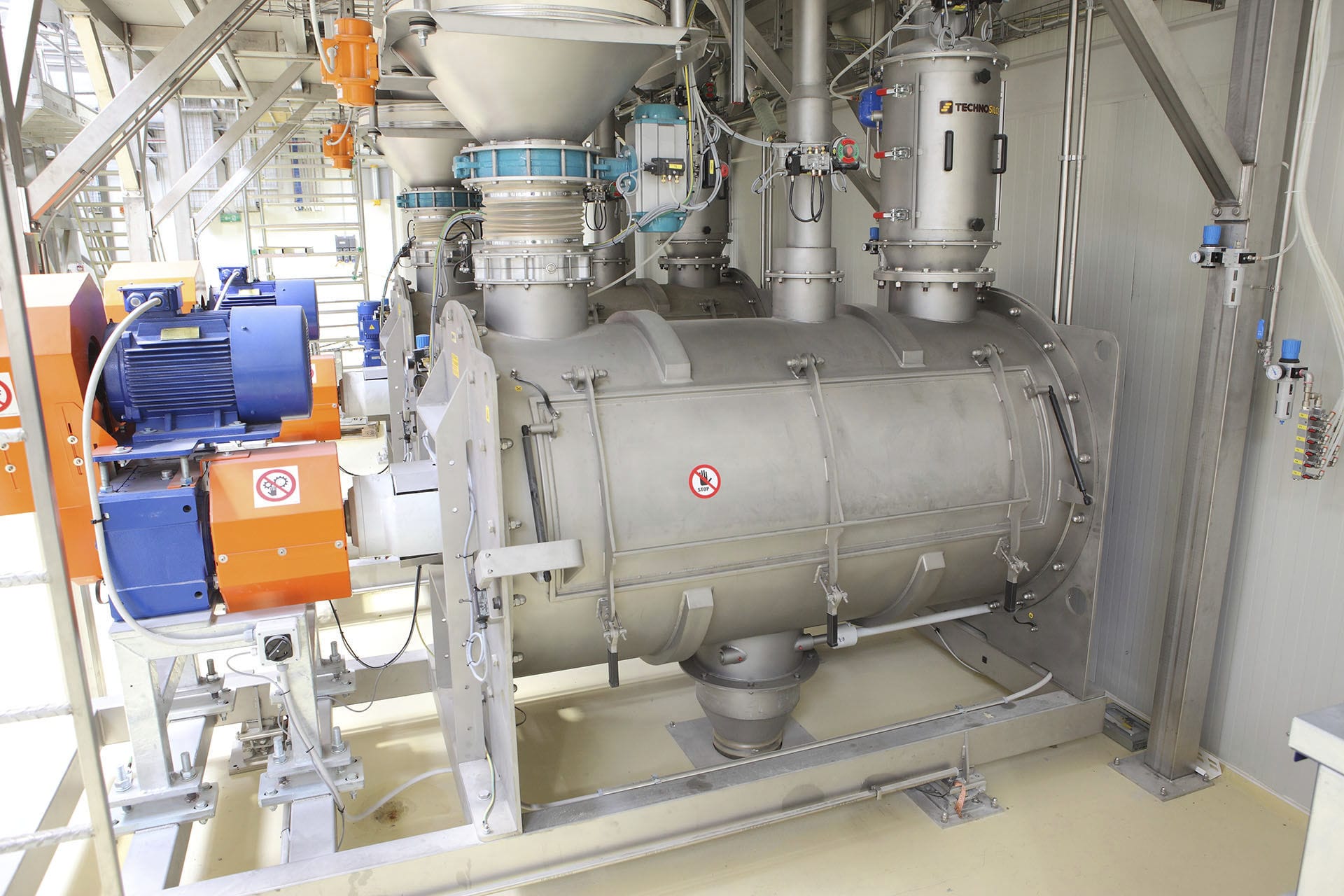
The reduction scale is fixedly connected to a silo through three Weighing modules. The silo has a silo inlet and a silo outlet, and the silo outlet is fixedly connected to the upper inlet of the outer cylinder. The outer cylinder is equipped with a propulsion component, and one end of the propulsion component is fixedly connected to a driving mechanism. The discharge part with a control valve is fixedly connected to the outer cylinder on the opposite end of the driving mechanism. The discharge section of the reduction scale is a T-shaped discharge pipe, and the lower surface of the outer cylinder is equipped with a first observation port for observing the appearance of the material output from the material bin discharge port. The upper end face of the T-shaped discharge pipe is equipped with a second observation port for observing the appearance of the pushed out material. The reduction scale weighing module is fixedly connected to the outer circumference of the feeding port of the silo. The reduction scale propulsion component is a propulsion screw, which drives the material based on the power output of the driving mechanism. The drive mechanism and the screw outer cylinder are fixedly connected through a quick release support component, and the control valve is a pneumatic rotary butterfly valve. The silo adopts a conical silo, and the discharge port of the silo is fixedly connected to the inlet of the outer cylinder through a heavy-duty quick clamp.
The weight reduction scale adopts a whole machine scale frame. The material is fed from the tail receiving section and passes through the weighing section of the scale body under spiral operation. The weighing module and speed sensor respectively measure the instantaneous weight and running speed of the material, and send it to the weighing controller for processing to obtain the instantaneous flow rate of the material. After software calculation, the PID control signal is output. Through frequency conversion adjustment, the feeding equipment or batching scale speed is controlled to achieve the set requirements of the material flow rate. The weight reduction scale is a quantitative feeding equipment that uses the rate of material reduction per unit time to calculate the material flow rate. It adopts static weighing and dynamic control methods, and is a high-precision measurement feeding control system. When the material in the hopper scale reaches the lower limit of weighing (or an empty scale), the discharge port is activated, and the material in the hopper is quickly dropped into the hopper scale. When the set upper limit is reached, the feeding port is activated, and when the feeding reaches the upper limit of weighing, the feeding is stopped to achieve the purpose of quantitative feeding. The accuracy and control precision of weighing have been improved by adjusting the feeding rate to adjust the feeding time and compensating for the difference.
Multiple devices can be connected to the upper computer system to form a distributed batching control. If the weight of the material in the weighing bin is greater than or equal to the upper limit set value, the machine will enter the batching state directly. If it is less than or equal to the lower limit set value, the Feeder will be opened to quickly feed into the weighing bin until the material in the weighing bin reaches the set upper limit. The feeding will stop when the material in the weighing bin reaches the set upper limit. The unloading of the weighing bin will be in a continuous working state. As the material in the bin continues to decrease, the instrument will perform anti PID control to make the instantaneous flow rate approach the set flow rate. When quickly feeding into the bin, the instrument will control the discharge and measurement in a volumetric control mode. The two control methods are periodically switched to achieve continuous quantitative feeding of the equipment.
Technical Parameters:
Hourly flow rate: 0-15t/h
System accuracy: better than 0.5% Environmental temperature: -20 to+50 ℃
Relative humidity:<90% RH (no condensation)
Instrument power supply: AC 187V-242V, 50Hz ± 1Hz
Main functions:
Control ingredients through dashboard settings
Controlled by the superior computer for ingredient preparation
Complete the control of the entire process of discharging and timing materials
The instrument can display cumulative, instantaneous, and output quantities, etc
The instrument can display daily, shift cumulative, and 2-year monthly cumulative values
More than 20 types of work status and error status indicators
Equipped with manual and automatic control functions
The instrument can output PID control signals and instantaneous flow current signals
Standard RS-485 computer communication interface