






Volume Mixing and feeding system uncertainties and internal and external interference as a whole for processing, the use of digital technology to compare and analyze it with the traditional PID controller, weighing controller to calculate the actual amount of feed, when the actual amount of feed to meet the feed set value to close the feed valve, from the whole process of action can be seen, the valve closure lag will inevitably lead to feeding error, the value of the error is about the lag time and the closure of the instantaneous volumetric flow rate, The error value is the product of lag time and instantaneous volume flow rate and fluid density at the time of closing, in which the lag time is all the time between the output of the valve closing signal from the weighing controller and the shut-off valve shutting down, "i.e., including the lag time of the relay's action and the shut-off valve's action lag time.

 020-34563445
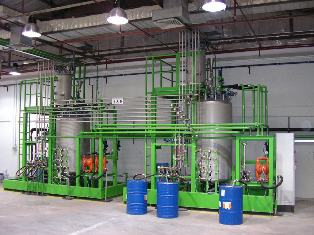
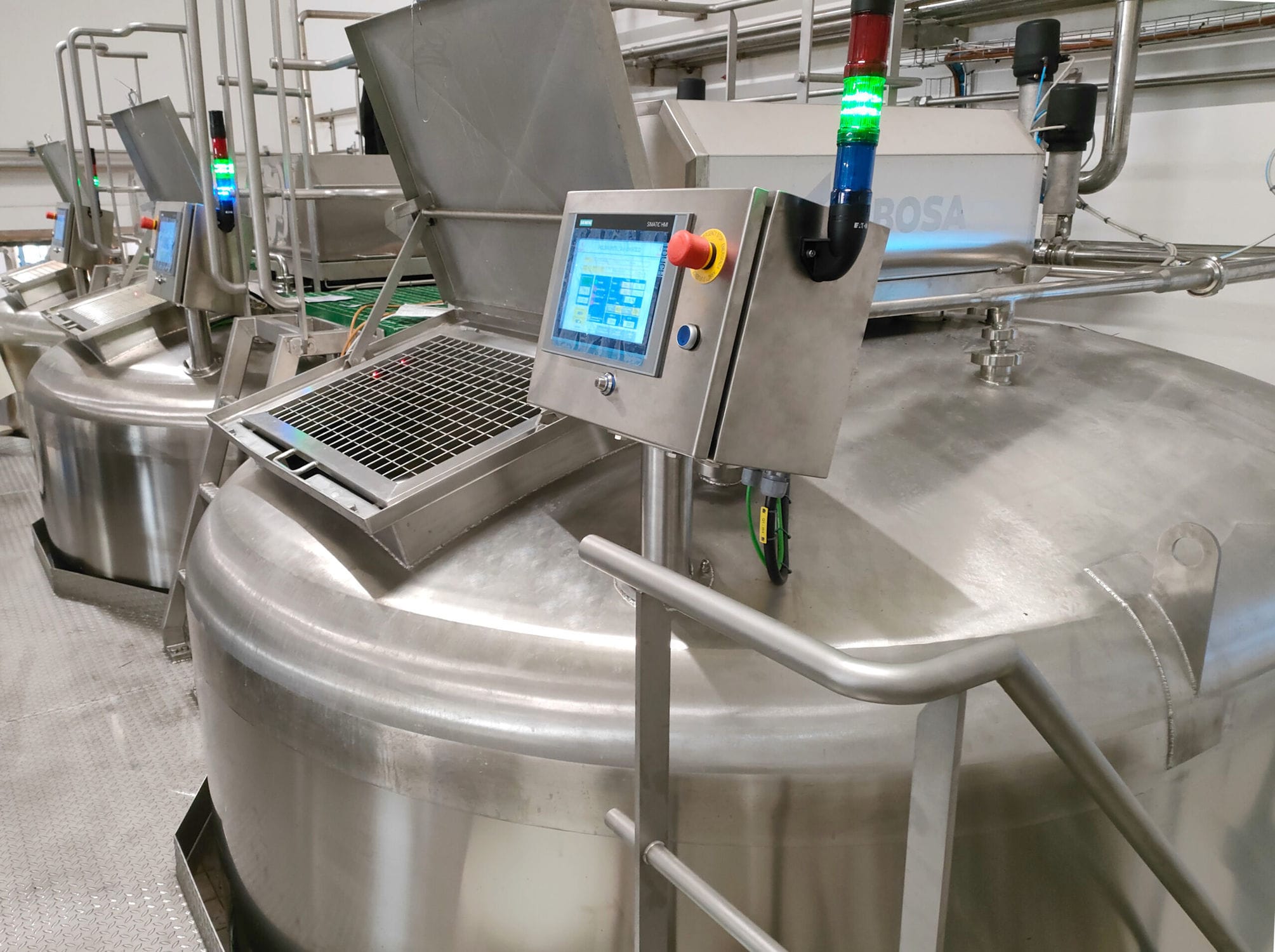
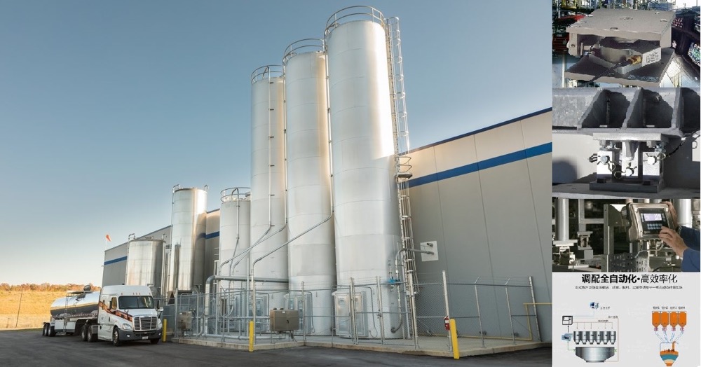
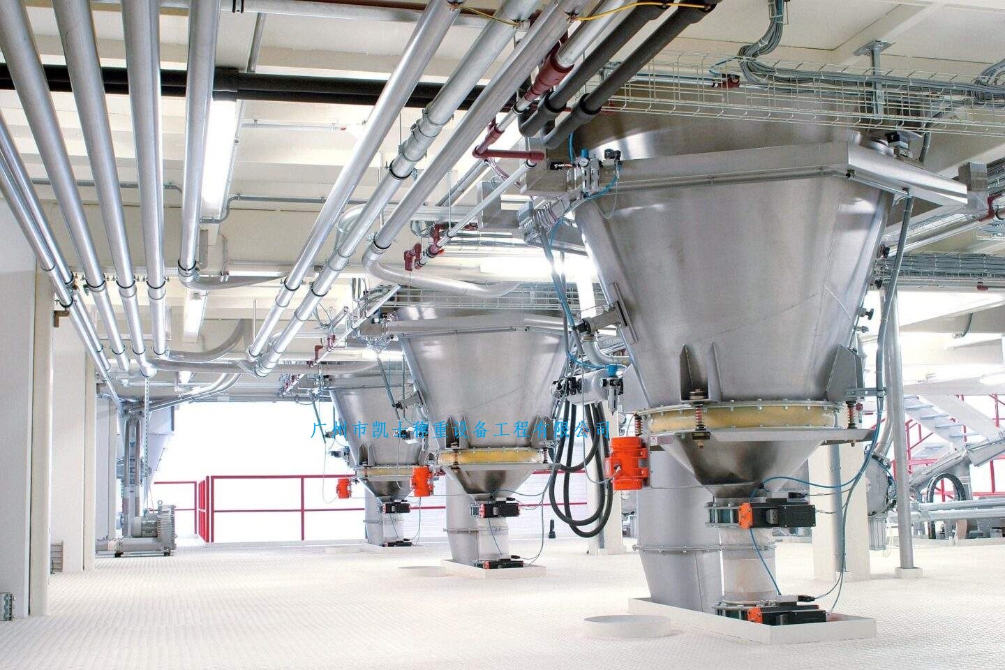
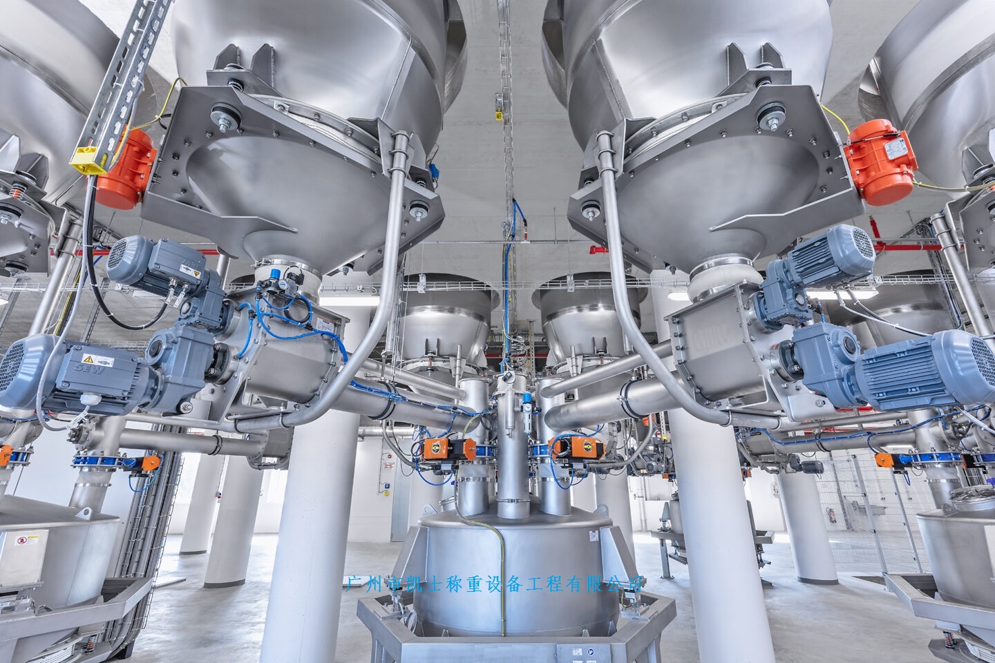
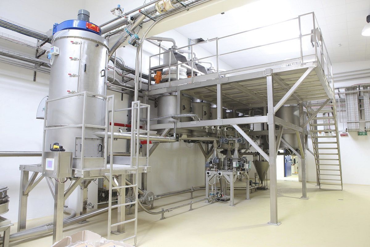
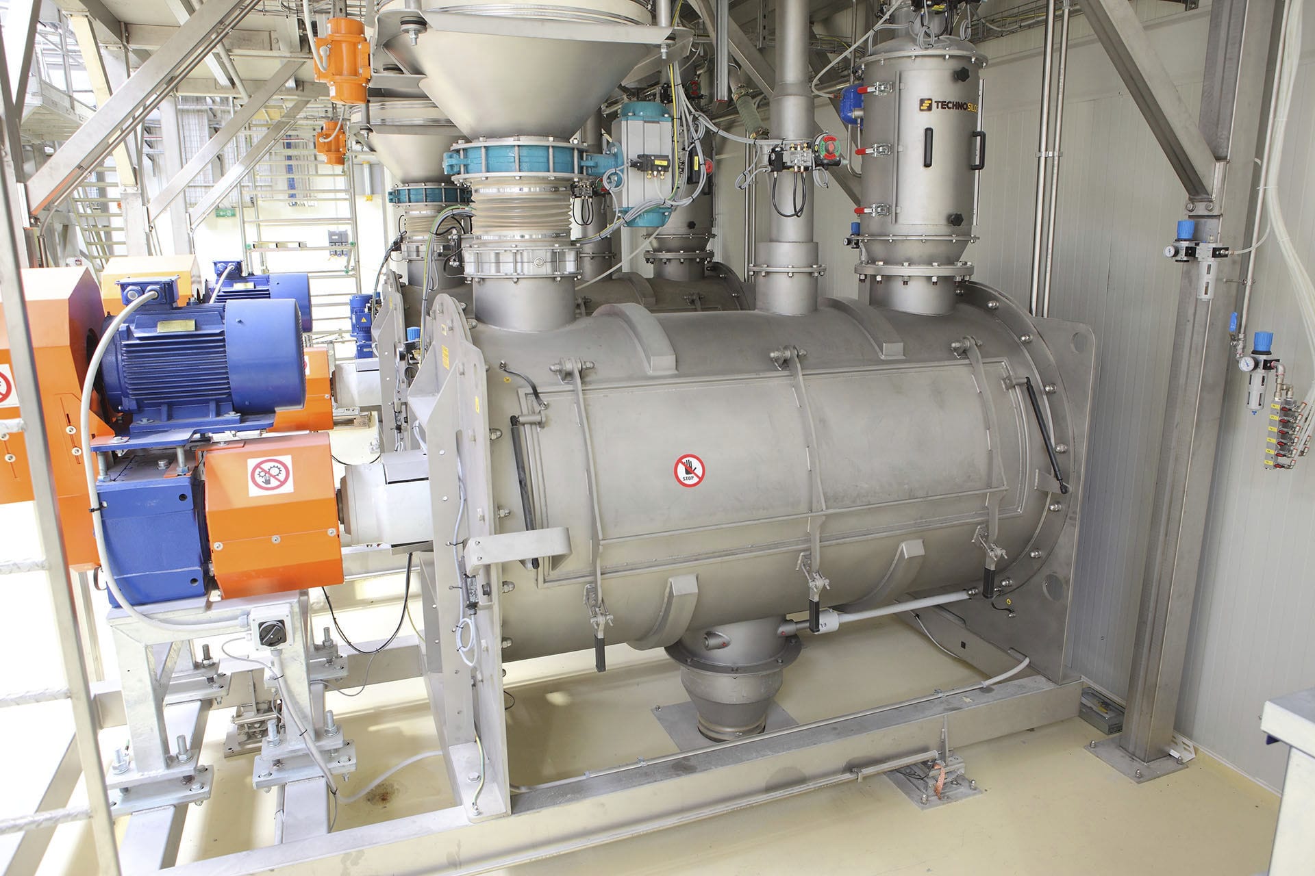
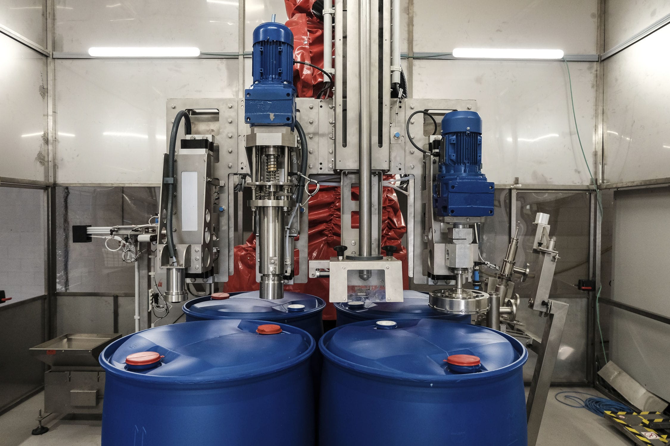
The volumetric mixing and feeding system is a complete set of automated equipment that achieves dynamic weighing and batching control through electrical control management and visual human-machine software configuration. The electrical control part of the system adopts Siemens PLC, which is programmed and controlled according to production requirements; The software adopts human-machine configuration and controls the weight and flow of materials loaded into the weighing hopper through monitoring system and PLC program according to process requirements, thereby achieving accurate measurement and batching. The system has strong stability and high cost-effectiveness, and can provide accurate measurement data and control methods for production control and management in various industrial sites. The uncertain factors and internal and external interference of the feeding system are treated as a whole, and digital technology is used to compare and analyze it with traditional PID controllers. The weighing controller calculates the actual feeding amount, and when the actual feeding amount reaches the feeding set value, the feeding valve is closed. From the entire action process, it can be seen that the valve closing action lag will inevitably cause feeding errors. The error value is about the product of the lag time and the instantaneous volume flow rate and fluid density at the time of closing. The lag time is the entire time from the output of the weighing controller to the closing signal of the cut-off valve, including the action lag of the relay and the cut-off valve. The feeding system is composed of Siemens series PLC, circuit breakers, relays, frequency converters, and terminals, all of which are selected from well-known domestic and foreign brands. Compact structure, stable operation, complete functions, with overload, short circuit, and phase loss protection, capable of completing equipment automation and process automation control. The system uses high-end configuration software as the upper computer to issue instructions and manage automation equipment and processes. Replacing traditional systems with standard industrial computer software and hardware platforms as integrated carriers has the characteristics of strong adaptability and good openness.
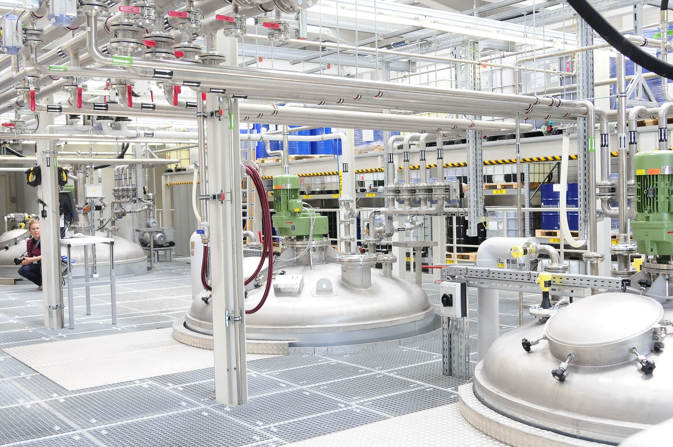
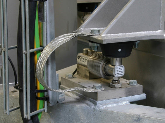
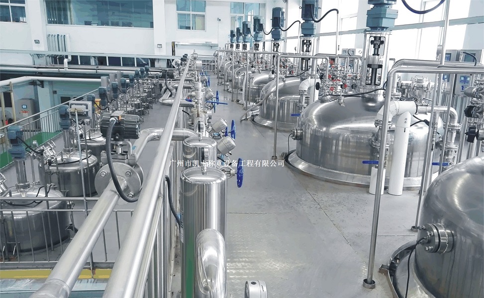
The weighing reaction kettle adopts multiple support ears welded on the outer wall of the reaction kettle, and the lower part of the multiple support ears is placed on the storage platform through multiple Weighing modules. One end of the multiple weighing modules is connected to the weighing instrument through a wire. A feeding tube is set above the feeding port of the reaction kettle, and the surface of the feeding tube can be disassembled and installed with an additive storage bin. There are multiple hopper scales inside the additive storage bin, and the bottom surfaces of the multiple hopper scales are fixedly installed with feeding tubes, and the surface of the feeding tubes is fixedly installed with weighing modules. The top surface of the reaction kettle is fixedly installed with a driving motor, and the output end of the driving motor extends vertically into the reaction kettle. A rotating rod is fixedly installed vertically, and the outer wall of the rotating rod is welded with a chain. The other end is fixedly installed with a stirring block. The upper end of the outer wall of the reaction vessel is fixedly installed with a cleaning pump through a mounting seat, and an electromagnetic valve is installed on the pipeline fixedly installed at the outlet end of the cleaning pump. The inner top surface of the reaction vessel is suspended with a cleaning pipe, and the bottom surface of the cleaning pipe is fixedly installed with a cleaning nozzle. The other end of the pipeline extends to the interior of the reaction vessel and is connected to the cleaning pipe. The upper and lower ends of the outer wall of the rotating rod of the reaction kettle scale are welded with connecting rods, and the end of the connecting rod near the inner wall of the reaction kettle is welded with a cleaning plate. The interior of the connecting rod is provided with a cavity, and the inner wall of the cavity is fixed with a spring through an installation plate. One end of the connecting rod extends into the cavity through a sealing piece and is fixedly connected to the other end of the spring. The inner wall of the cavity is provided with a limit groove, and the internal sliding connection of the limit groove is connected to a limit block, and one end of the limit block is welded to the outer wall of the connecting rod.