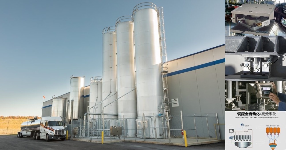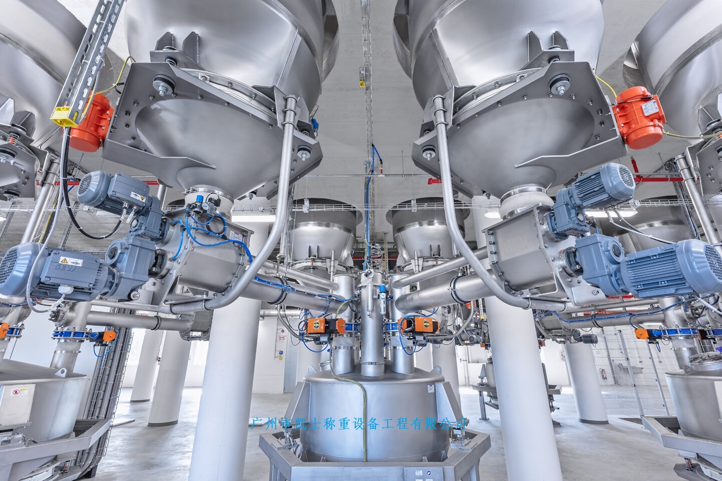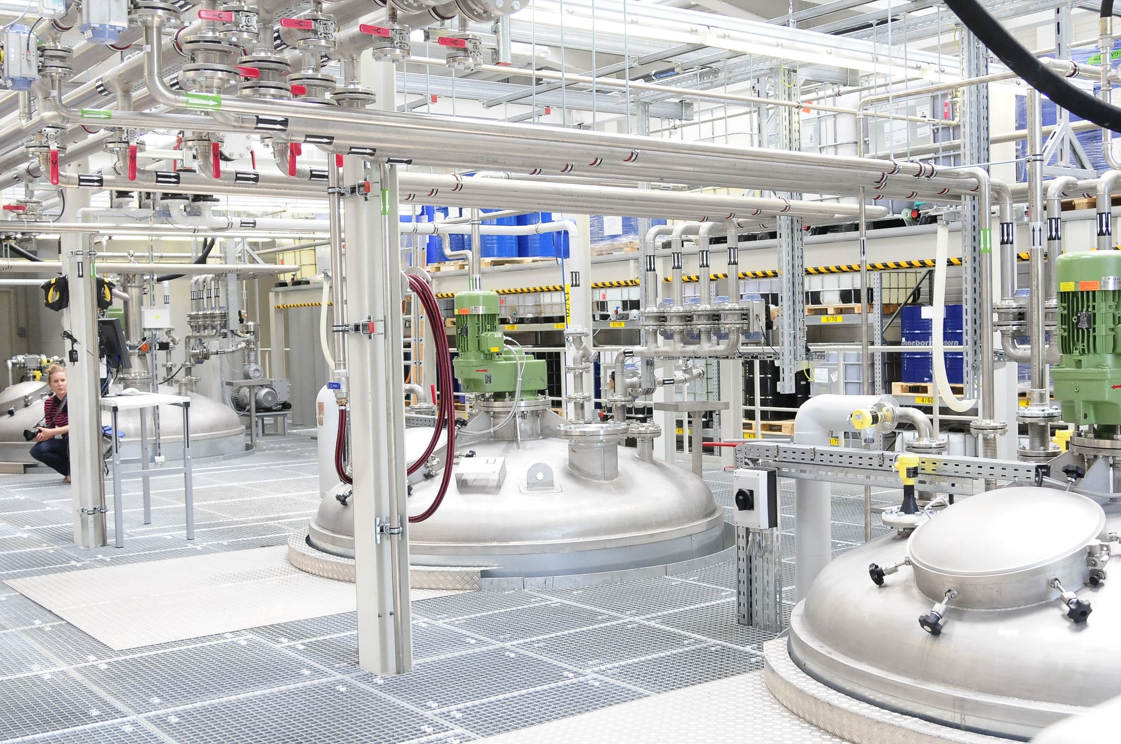





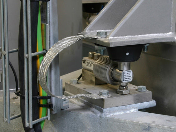
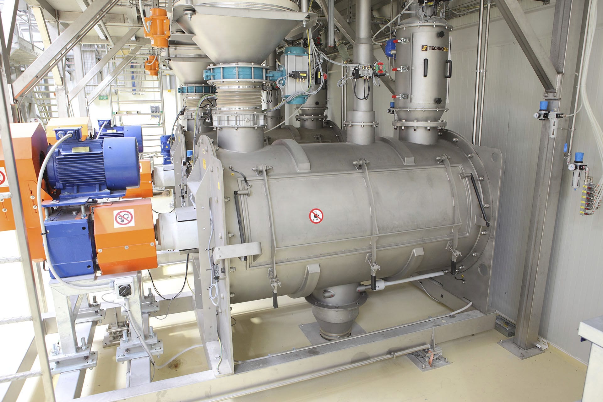
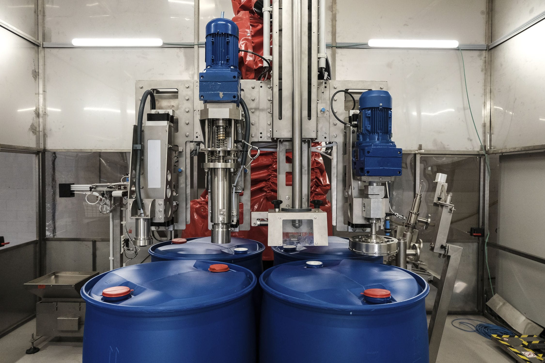


The frequency modulation automatic batching system measures the powder quantity by using the weighing module and the rotational speed of the screw conveyor. The screw conveyor in the measurement unit operates at a constant speed. The rotational torque of the screw conveyor is transmitted to the weighing module through the silo. The output voltage of the weighing module is proportional to this rotational torque, and it is converted from analog to digital form through an analog-to-digital converter. The rotational speed of the screw conveyor is measured by the speed-weighing module and converted into a digital quantity through a frequency converter. Finally, the rotational torque and speed are input into the weighing instrument for calculation, thereby obtaining the instantaneous flow rate of the powder.


 020-34563445
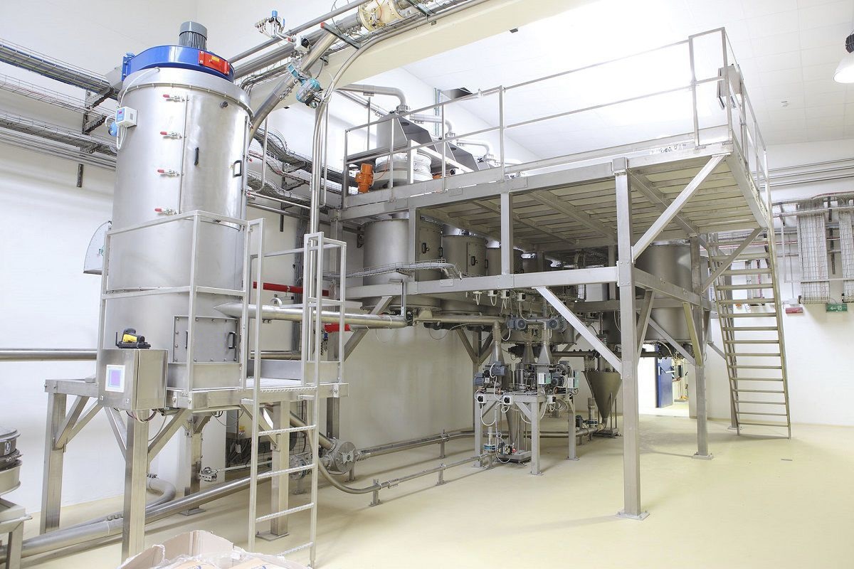
The automatic frequency modulation Batching system uses PLC as the lower computer, which communicates with weighing instruments and frequency converters to collect, process on-site data and perform simple control. PLC communicates with the upper computer through Ethernet modules to exchange system operation data. In the lower computer, it mainly completes the display, processing, and setting of various powder weighing on site; Recording, storing, and querying on-site data, and alerting important data; Simulated operation at the production site; The setting of ingredient formulas and the simulation operation of spiral conveying. Complete data collection and control of powder weighing, batching, and feeding processes, and achieve monitoring of material weighing, batching, and feeding processes. The batching system uses the weighing module and the speed of the screw machine to measure the powder. The screw machine of the measuring unit operates at a constant speed and has multiple small bins distributed along the guide cone. During the rotation of the screw machine, the powder flows along the conical distributor at the center of the screw machine to each small bin, and then slides down the measuring bin wall into the curved discharge pipe. The rotational torque of the screw machine is transmitted to the weighing module through the silo, and the output voltage of the weighing module is proportional to the rotational torque. The analog quantity is converted into digital quantity output through analog-to-digital conversion. The speed of the screw machine is measured by the speed measurement and weighing module, and converted into a digital quantity through a frequency converter. The final rotational torque and speed are transmitted to the weighing instrument for calculation, thereby obtaining the instantaneous flow rate of the powder.
The ingredient system can be decomposed into three units: a setpoint control unit, a PID action unit, and a manual/automatic switching unit. The fixed value unit I receives the flow measurement value of the screw conveyor and the given value of the control device. The PID action unit receives the error signal generated by the given value control unit and calculates the closed-loop control signal according to the given control law. When the manual automatic unit is in the "automatic" position, the output signal of the PID unit is sent to the industrial process, and the industrial process is controlled in the closed-loop. When in the "manual" position, the manual signal adjusted by the user directly on the controller is sent to the industrial process, so the system belongs to the open-loop control mode. The batching system adopts frequency converter control, with dual control functions of on-site manual and centralized control by the upper computer, to control the feeding amount of the screw Feeder. The feeding amount is mainly determined by the speed of the screw and is linearly proportional to the speed of the screw. When in manual operation mode, the operator can manually adjust the potentiometer on the operation box to control the frequency of the frequency converter, thereby controlling the speed of the screw feeder. When in automatic operation mode, the personnel in the batching control room can set the flow rate to the PLC from the upper monitoring computer, and at the same time, the screw conveyor measures an actual flow signal and feeds it back to the PLC for PID calculation. Finally, a control quantity is obtained, and the speed of the screw feeder is controlled by the frequency converter to achieve the purpose of controlling the material flow rate.
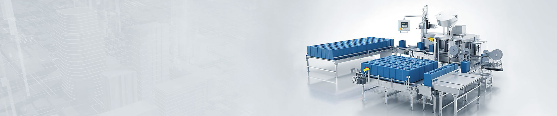
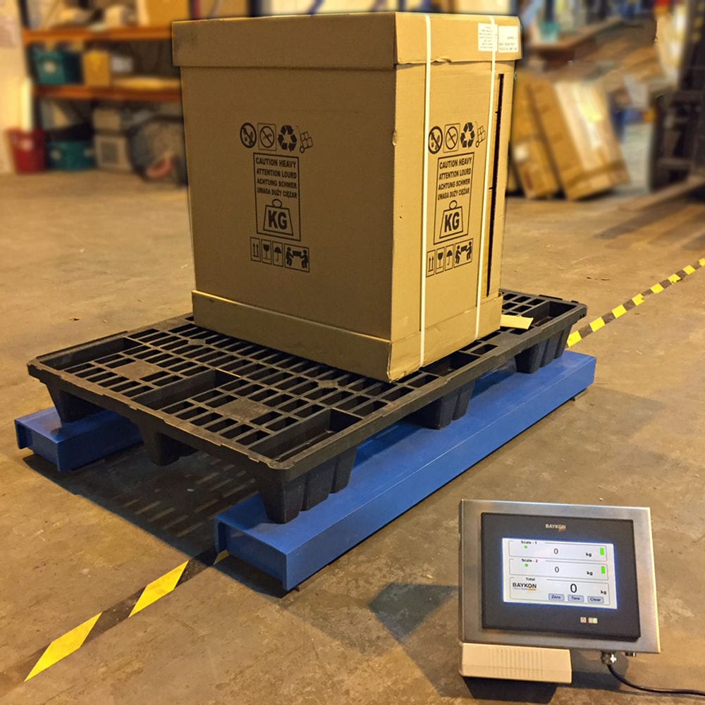
The weighing and batching machine adopts a weighbridge for measurement. Multiple batching tanks are fixed horizontally on the upper part of the weighbridge, and electromagnetic valves are installed at the lower outlets of the batching tanks. A horizontal guide rail is fixed in the middle of the weighbridge, and a collection bin is connected to the guide rail for sliding. The collection bin is connected to a driving device that drives it to move horizontally on the guide rail. There are pull rods fixed on both sides of the collection bin, and the free ends of the two pull rods are connected to the winding wheel motor on the adjacent side. Both sides of the aggregate bin are equipped with positioning rings located between the aggregate bin and the first wheel. The positioning rings are located outside the stroke of the aggregate bin, and the center of the positioning ring is at the same height as the fixed connection between the pull rod and the aggregate bin. There is a positioning ring fixed on the weighing scale between the positioning ring and the adjacent winding wheel, and the center of the positioning ring is at the same height as the axis of the winding wheel. The lower part of the aggregate bin is equipped with a discharge port, and an electromagnetic valve is also installed at the discharge port. The upper part of the aggregate bin is fixed with a bracket, and there is a weighing bin inside the aggregate bin. The two sides of the weighing bin are installed on the bracket through Weighing modules. The lower part of the weighing bin is equipped with a discharge port, and an electromagnetic valve fixed on the weighing bin is installed at the discharge port. Symmetrically arranged winding wheels are installed on both sides of the weighing scale, and stepper motors are installed on both sides of the weighing scale. The output shaft of the stepper motor is coaxially fixed to the winding wheel on the corresponding side through a connecting shaft.