


The automated emulsion filling machine achieves filling into containers. The rotor pump's movement controls the feeding process. An electronic scale is installed at the bottom of the container. The input voltage is adjusted by a variable resistor. After comparing the input signal with the feedback signal from the electronic scale, a control signal is formed. This signal is then regulated by PID and amplified before being used to drive and control the proportional valve. The rotational speed of the rotor pump is achieved in a closed-loop manner.


 020-34563445
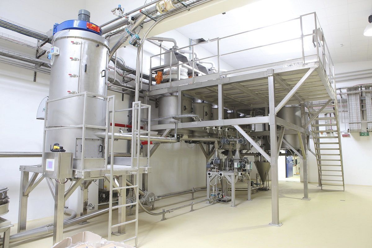
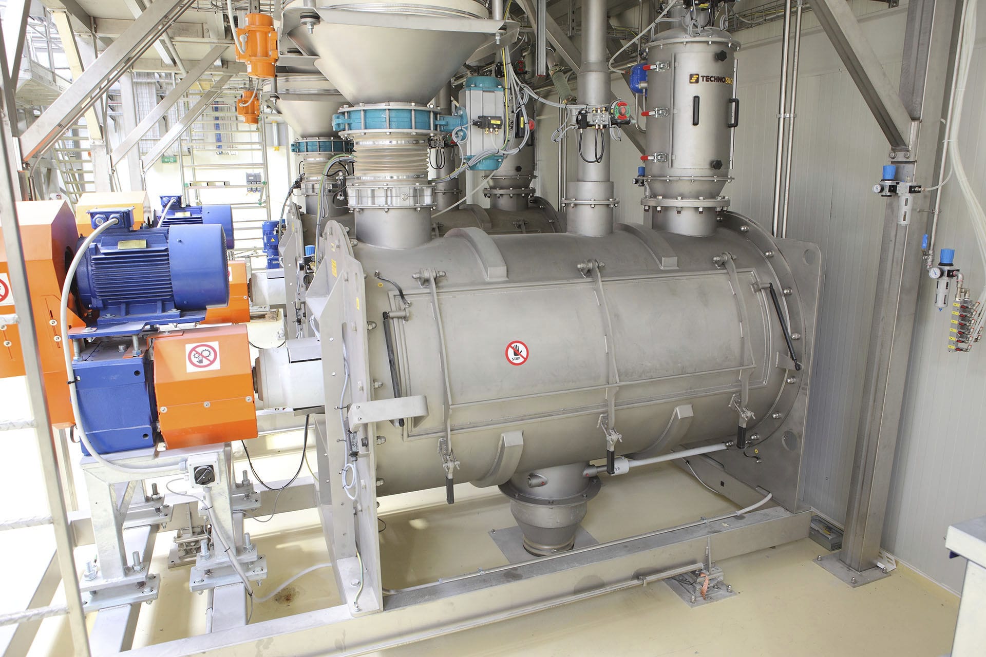
The automated emulsion Filling machine is composed of filling, sealing, boxing, palletizing, weighing equipment, along with corresponding conveyor belts, supplemented by automatic control and automatic adjustment systems. When a 4-liter bucket reaches the feeding conveyor belt, the rotor pump bucket separator separates the bucket and sends it to the fixed scale platform under the fixed oil injection nozzle of the rotating tank, where quantitative filling is carried out by symmetrically configuring the piston cylinder around the rotating tank. Each piston is connected to an axle through a connecting rod and slides along an inclined circular trajectory. The first 180 degrees of the inclined circular motion causes the piston to rise, and the last 180 degrees causes the piston to descend. When the piston rises, the material is controlled by the valve to be drawn into the piston cylinder from the upper oil tank. When the valve connecting the piston cylinder and the oil injection nozzle is opened, the material is injected into the bottom bucket, and the current filling quality, filling bucket number, and other on-site working conditions are displayed in real time through the screen. Through PLC communication on the upper computer, corresponding operations are carried out simultaneously. Through the interface, the selection of filling mode, start, stop, emergency stop, and operation of buttons such as start and stop are performed. It is possible to change the filling quality, bucket number, and manually remove the skin weight (i.e., the filling bottle's weight) when using different filling buckets. To meet the above monitoring requirements, the monitoring interface simulates the dynamic filling process by setting the filling effect and fast flow properties; by adding standard buttons, manual/automatic selection, start, stop, emergency stop, and manual opening of the pump electromagnetic valve are achieved. Through the display output attribute of the label settings, the setting of filling quality, the setting of the current filling bucket number, and the display of the current filling bucket number are realized. The configuration monitoring interface monitors the operating status of the Filling system through these group configuration monitoring diagrams.
In the automatic filling machine, the material supply uses an inlet and outlet rotor pump. The rotor pump is driven by a frequency converter through a motor. The operating speed and start/stop of the rotor pump are controlled based on the current weighed weight and the target weight. When the weighed weight reaches the allowable error of the target weight, the rotor pump switches to cycle feeding. The target weight for weighing can be controlled through the upper computer or directly input by the touch screen. The lateral movement is achieved by the rotor pump's rotational speed, and the filling is controlled by the rotor pump's movement. The entire operation process starts from the initial point where an Electronic scale is installed at the bottom of the container. First, the amount of material in the container is detected within the range, and the height of the liquid level in the container is also detected. When there is enough material in the container but the liquid level is low, the Feeding machine of the rotor pump starts, the lateral movement begins, the rotor pump reaches the end of the lateral movement, and then starts to feed the material to the filling port of the container. The height of the liquid level in the container is detected, and the input voltage is adjusted by a variable resistor. The input signal and the feedback signal from the electronic scale are compared to form a control signal, which is then regulated by PID and amplified to drive and control the proportional valve. The rotor pump's rotational speed is achieved in a closed-loop control.
The Liquid filling machine and filling gun cylinder drive are driven by the rotor pump feeding system and the filling gun cylinder drive system. The rotor pump feeding system and the filling gun cylinder drive system adopt variable frequency filling and feeding. The maximum pressure of the system is adjusted by the safety valve. The pressure of the liquid in the hydraulic pipe is controlled by the electromagnetic directional valve to achieve the precise position control of the filling gun and the forward rotation of the hydraulic rotor pump and the opening and closing of the filling gun. The drive system also adopts variable frequency rotor pump feeding. Two pilot relief valves on the two-way cartridge valve block set the two system material pressures. The forward rotation of the electromagnetic directional valve is realized. The priority quantitative control of variable frequency rotor pump power control is given priority. If the set flow rate or working pressure exceeds the power curve, constant power control replaces the electrically controlled variable frequency and reduces the displacement according to the constant power curve. When below the power curve, the displacement is controlled by the adjustment of the control current. The rotor pump output flow is only related to the input control signal and is not affected by the load pressure change. The drive rotor pump achieves overpressure protection through two built-in relief valves. The inlet and outlet of the rotor pump are connected to the two ends of the shuttle valve, and the electronic scale detects the inlet weight of the rotor pump as the control signal and feeds it back to the controller.


