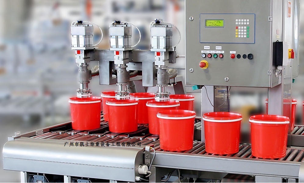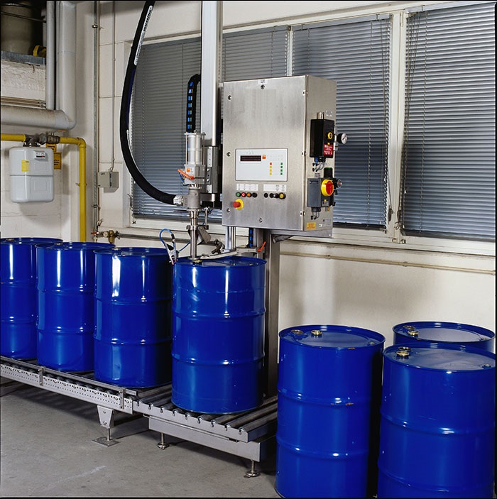


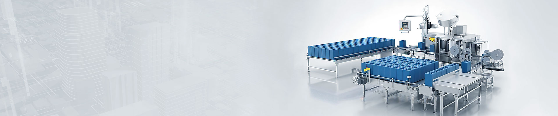
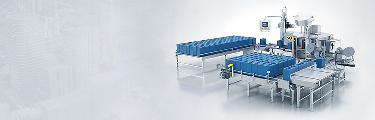


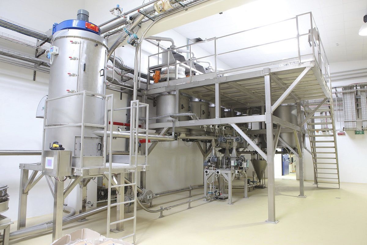
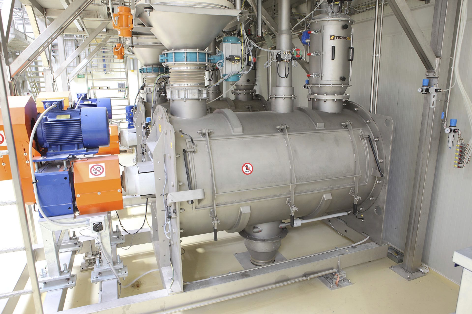
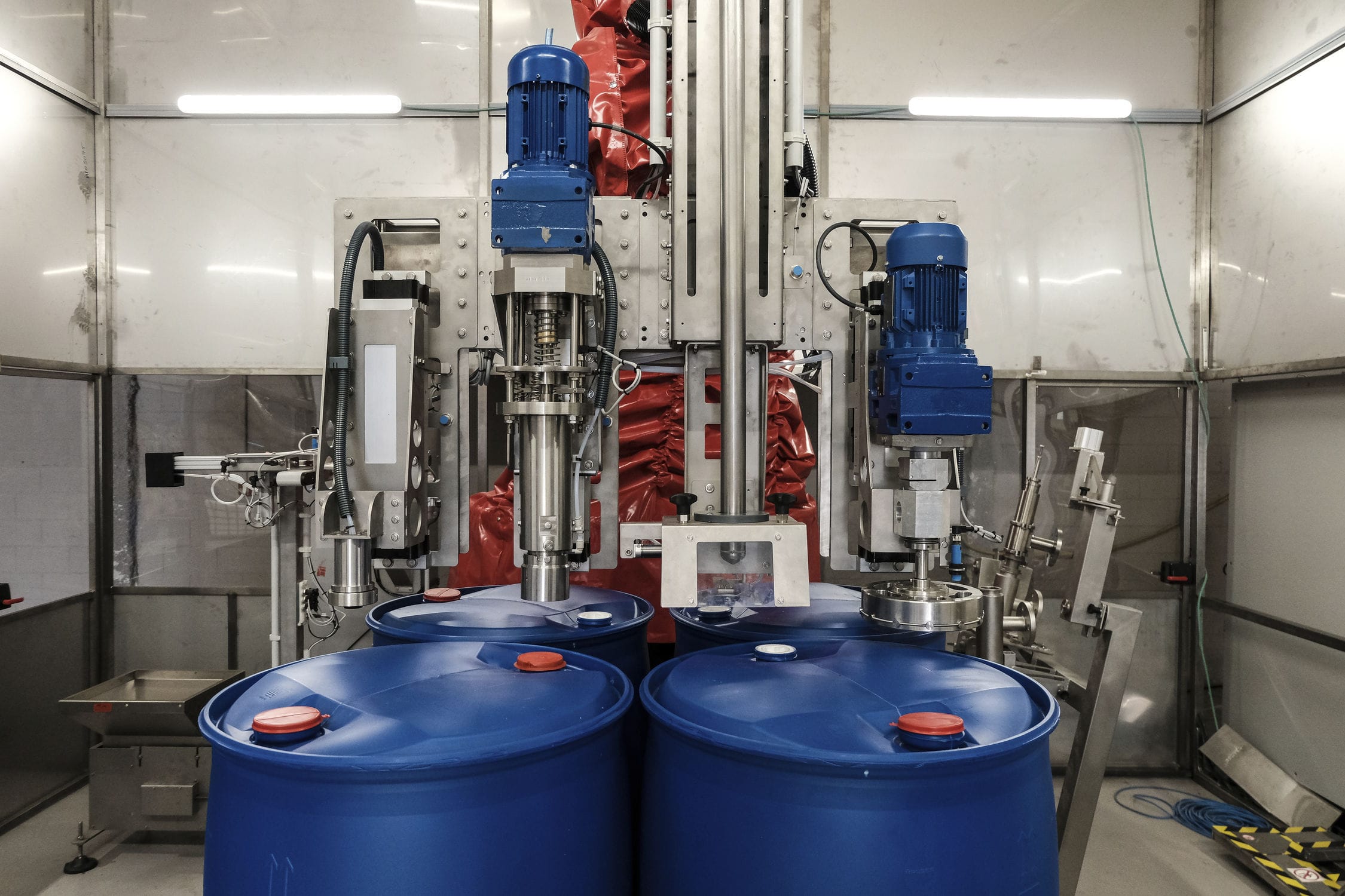
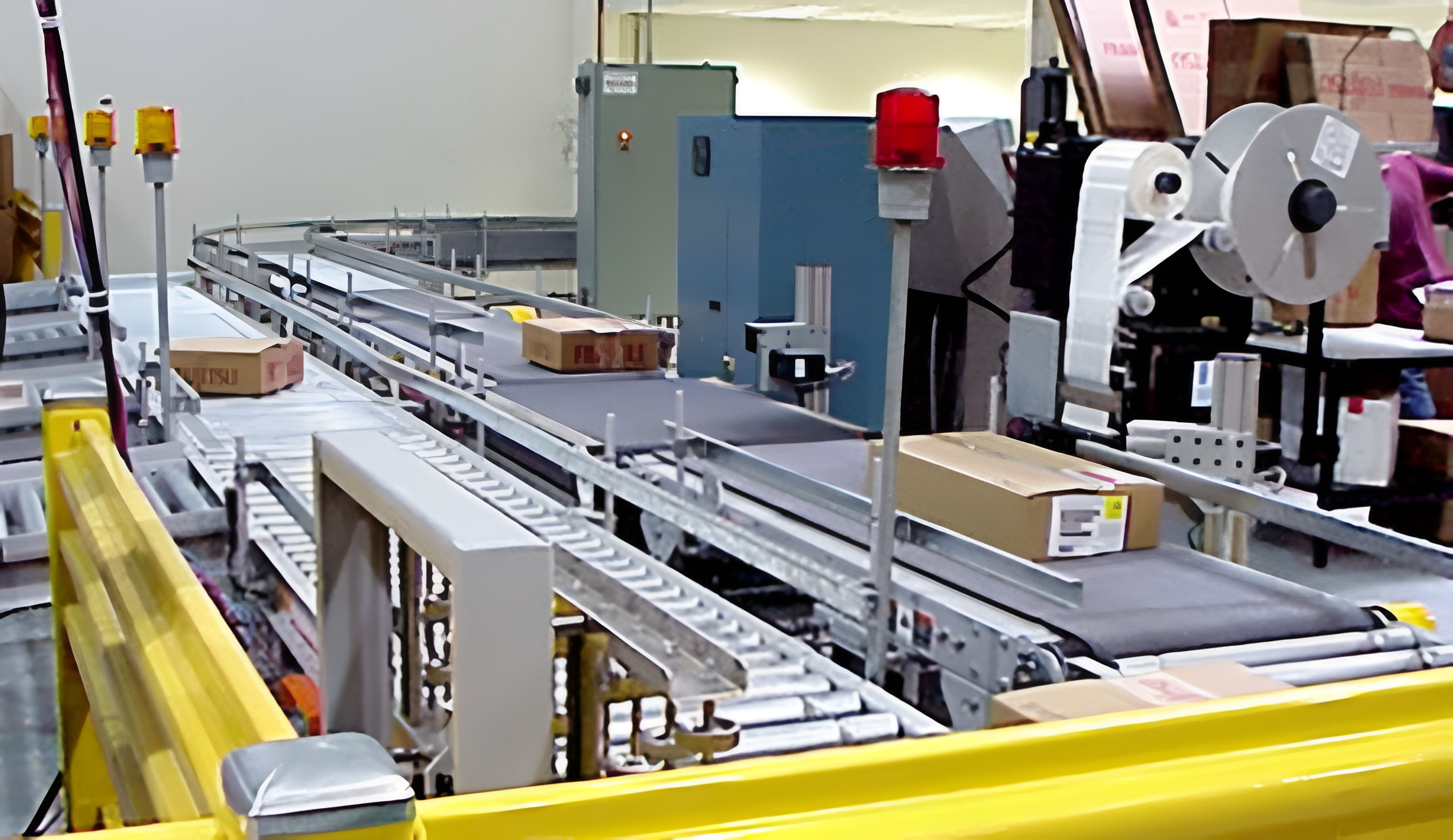


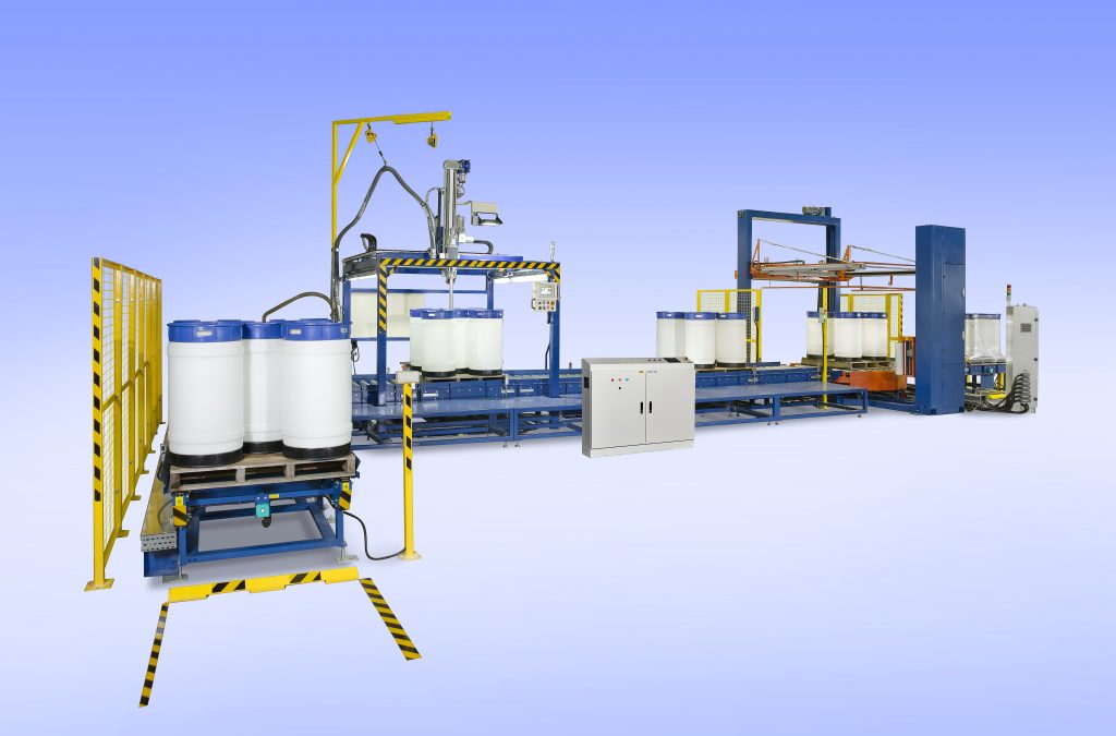
The liquid methanol auxiliary filling and packaging machine adopts a two-stage automatic quantitative filling method and one-button operation mode: start - the filling gun descends - automatic skin removal - start filling - complete filling - the filling gun rises. It is manufactured with high-end electrical components such as PLC programmable controllers. It uses a two-stage automatic filling method for large and small materials, and employs automatic weighing, filling cylinder system, filling gun piston and other automation technologies. It has an intelligent filling weighing and inventory management system to prevent incorrect material filling during the filling process, ensuring that each batch of filling data is recorded and traceable. It also follows the first-in-first-out principle when raw materials are released, effectively solving the waste of raw materials.

 020-34563445
The liquid Filling machine refers to a Weighing system that integrates weight information collection, amplification, transformation, transmission, processing, and display. It controls various sensors, relays, switches, and solenoid valves through a PLC program, drawing on advanced processes and technologies and combining long-accumulated experience to integrate inventory management, filling management, filling weighing, process control, product traceability, and other aspects. It adopts a two-stage automatic quantitative filling method for both large and small materials and a one-click operation mode: start - filling gun descends - automatic peeling - start filling - filling gun rises. It is manufactured with high-end electrical components such as PLC programmable controllers, utilizing automatic weighing, filling cylinder systems, filling gun pistons, and other automation technologies, intelligent filling weighing and inventory management systems to prevent material errors during filling, ensuring that each batch of filling data is traceable and following the first-in first-out principle when raw materials are released from storage, effectively solving the waste of raw materials. The automatic filling machine completes the feeding of raw materials into each container and the collection of weighing signals according to the filling parameters and feeding sequence. The frequency converter is set to multiple speed segments, with the frequency controlled by the output points of the PLC. When the filling gun is filling, the PLC controls the filling gun motor to operate at the high-speed segment of the frequency converter. When the amount of raw material approaches (filling amount - retention amount), the PLC output points control the filling gun motor to operate at the low-speed segment of the frequency converter for slow feeding. During the feeding process, the PLC compares the amount of raw material with (filling amount - retention amount) in real time. If it is within the tolerance range, the feeding is stopped; when it approaches the target tolerance value, the frequency converter is operated at the low-speed segment for feeding. The filling gun generally has two feeding speeds: fast and slow. Fast feeding is used at the beginning of filling, and the fast feeding advance amount is used to determine the feeding amount for the slow feeding process. After reaching the set value, slow feeding is used, and the slow feeding advance amount is used to compensate for the impact of flying materials in the air, making the weighing value as close to the set value as possible. By setting the filling gun according to the actual production process and reasonably setting the fast and slow feeding advance amounts, the filling accuracy can be better controlled. Through controlling the filling process, the control advance amount is set according to the error conditions of multiple measurements for different materials.
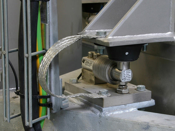
The quantitative filling machine is equipped with a filling device that includes a conveying hydraulic cylinder installed at the top. The filling machine is equipped with a PLC Filling system. The conveying hydraulic cylinder is equipped with a filling valve, and the lower part of the filling valve is equipped with a liquid outlet piston valve. Corresponding to the liquid outlet piston valve, a weighbridge is installed below the filling machine. The electronic weighbridge is fixed behind the barrel inlet. Each empty barrel is conveyed by the barrel conveyor chain into the main machine's weighing platform under the action of the barrel inlet conveyor, and as it is conveyed along the center of the weighing platform, it passes through the weighbridge, which sends a signal to the PLC controller. Then, the PLC sends a command to open the filling valve to start the filling process. A pressure stabilizing tank is independently installed on one side of the filling machine to supply liquid to the conveying hydraulic cylinder. A liquid supply pipe is installed between the conveying hydraulic cylinder and the pressure stabilizing tank. The lower end of the liquid supply pipe is equipped with a liquid supply pump controlled by the PLC. The PLC controls the liquid supply speed of the pressure stabilizing tank by adjusting the speed of the liquid supply pump. The end of the horizontal liquid inlet pipe between the conveying hydraulic cylinder and the pressure stabilizing tank is connected to the liquid inlet pipe of the conveying hydraulic cylinder through a conveying connector. A horizontal partition plate is installed in the middle of the conveying hydraulic cylinder. The liquid inlet pipe of the conveying hydraulic cylinder passes through the horizontal partition plate downward. An air cylinder that drives the opening and closing of the filling valve is installed on the horizontal partition plate. An electromagnetic valve that controls the opening and closing of the air cylinder is installed on the air supply pipeline of the air cylinder. The air supply pipeline is connected to the air cylinder through an air pipe joint. The top of the conveying hydraulic cylinder is equipped with a power supply device and an air supply device, responsible for supplying power and air to the electromagnetic valve and air cylinder matched with each filling valve. An overflow chamber is installed in the lower and middle area of the conveying hydraulic cylinder 3. The bottom of the overflow chamber is connected to the pressure stabilizing tank through a pipeline. Each filling valve in the conveying hydraulic cylinder is surrounded by a pressure stabilizing cover. The top edge of the pressure stabilizing cover is higher than the set liquid level line. The surrounding area of the pressure stabilizing cover is equipped with a liquid inlet hole. The lower edge of the pressure stabilizing cover is surrounded by an overflow groove. The top edge of the overflow groove is flush with the set liquid level line. A connecting pipe is installed between the overflow groove and the overflow chamber to control the liquid level of the hydraulic cylinder. The horizontal partition plate is equipped with an overflow chamber liquid level sensor that extends into the overflow chamber and a liquid level sensor that extends into the hydraulic cylinder. The overflow chamber liquid level sensor and the hydraulic cylinder liquid level sensor are signal-connected to the PLC controller. An overflow chamber top baffle is also installed on the transverse diaphragm. The perimeter of the overflow chamber top baffle is larger than that of the overflow chamber, to prevent liquid from directly entering the overflow chamber and reduce the impact of liquid inlet. A gap is provided between the overflow chamber top baffle and the top opening of the overflow chamber. A liquid level stabilizer is installed on the top and outer circumference of the overflow chamber to prevent the impact of liquid supply on the liquid level in the liquid cylinder, thereby stabilizing the liquid level in the delivery liquid cylinder 3. The top edge of the stabilizer is higher than the top edge of the overflow chamber top baffle, and the bottom edge is lower than the top edge of the overflow chamber 1. Gaps are provided between the stabilizer and the overflow chamber top baffle as well as the perimeter of the overflow chamber. The stabilizer can be supported on the top edge of the overflow chamber through its bottom bracket, or on the overflow chamber top baffle through a bracket. A pneumatic liquid supply ball valve controlled by a PLC controller is installed on the liquid inlet pipe of the pressure stabilizing tank, and a liquid level sensor controlled by a PLC controller is installed inside the pressure stabilizing tank.
The filling valve of the quantitative filling machine extends through the middle and bottom of the conveying liquid cylinder and is installed on the inner side of the cylinder's periphery. The valve body serves as the fixed base component of the filling valve, which is pressed onto the bottom plate of the conveying liquid cylinder via the valve body seal ring. The top and upper periphery of the valve body are connected to the inner cavity of the conveying liquid cylinder. The outer end of the valve body is fastened to the bottom plate of the conveying liquid cylinder with an end nut. The bottom of the end nut is sealed and connected to the liquid outlet piston valve via a clamp. The valve body is sealed by the liquid outlet piston valve seal ring and the liquid outlet piston valve. The inner hole of the valve body is equipped with a lifting rod, which moves up and down. The lower end of the lifting rod is fitted with a flow guide that matches the inner cavity of the liquid outlet piston valve. A flow guide seal ring is provided on the outer peripheral surface of the bottom end of the flow guide. A lifting rod guide sleeve is installed inside the valve body's inner cavity, and the lifting rod is fitted inside the guide sleeve. A spring, fitted on the lifting rod, is positioned between the flow guide and the lifting rod guide sleeve. When the valve is opened, the flow guide, along with the flow guide seal ring, is lifted by the lifting rod, forming a roughly 4mm gap with the inner conical surface of the liquid outlet piston valve. When the valve is closed, the flow guide, along with the flow guide seal ring, is pushed down by the dual action of the cylinder and spring, pressing against the inner conical surface of the liquid outlet piston valve to form a tight seal. The valve closes, and the liquid is stopped. A cylinder base is mounted on the transverse diaphragm in the middle of the conveying liquid cylinder. An adjusting nut is mounted on the upper end of the cylinder base, and an air cylinder is mounted above the adjusting nut. The lower end of the piston rod is fitted with a threaded joint and a fine thread nut. The spacing between the lower end surface of the adjusting nut and the upper end surface of the fine thread nut determines the degree of valve opening. A buffer pad is installed between the fine thread nut and the adjusting nut to provide a cushioning effect during valve opening limit. The lower end of the threaded joint is connected to the ball head on the upper end of the lifting rod via a centering nut and a lock nut, ensuring smooth movement by automatically centering the ball head during the lifting rod's up-and-down motion. A corrugated tube is installed between the lifting rod and the cylinder base to seal the installation opening of the filling valve on the transverse diaphragm in the middle of the liquid cylinder.