



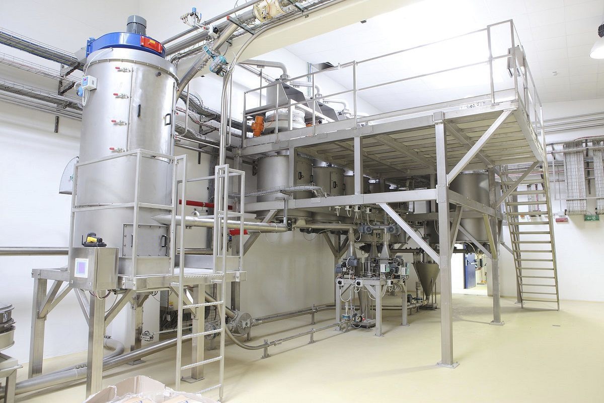
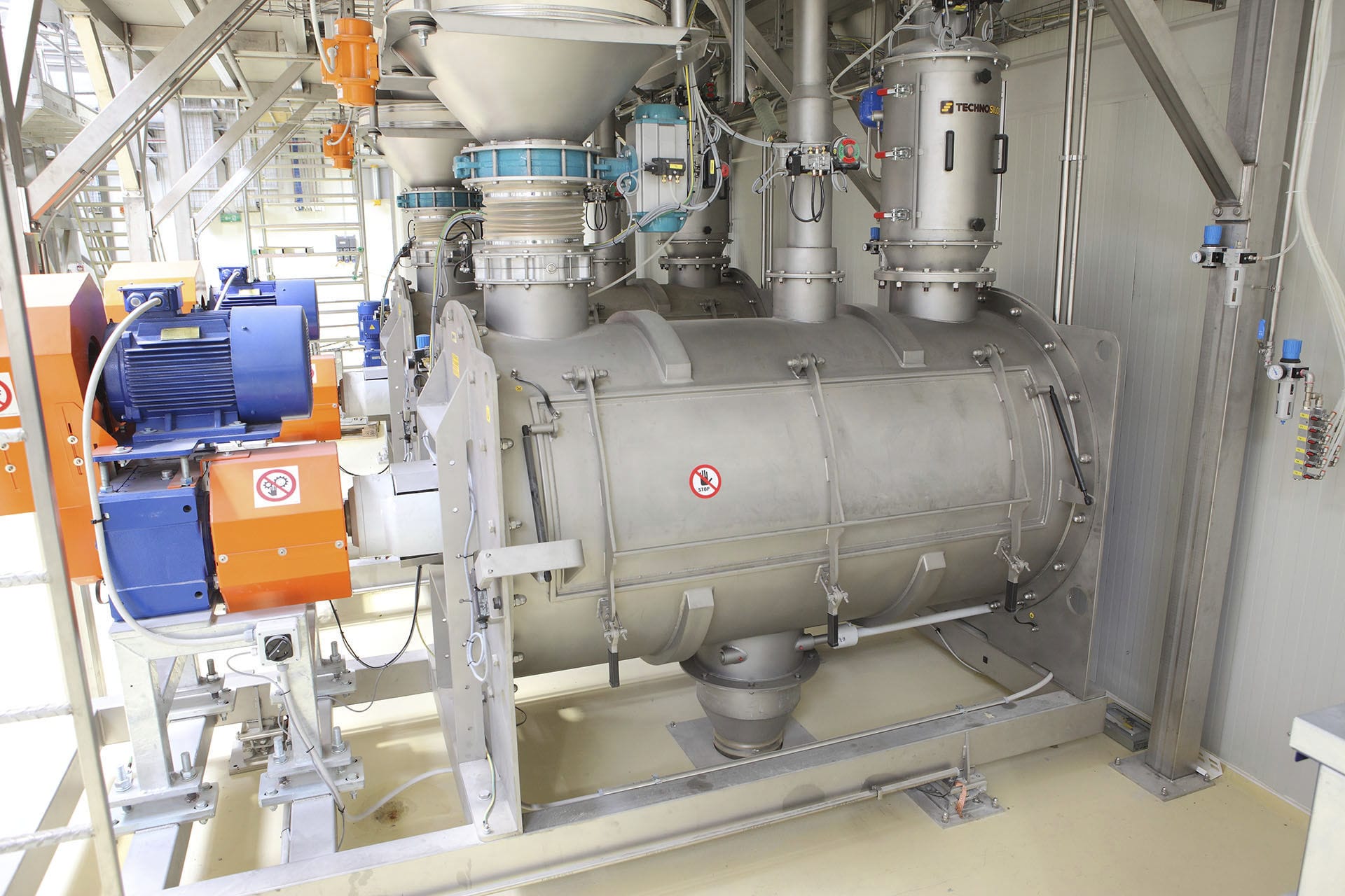
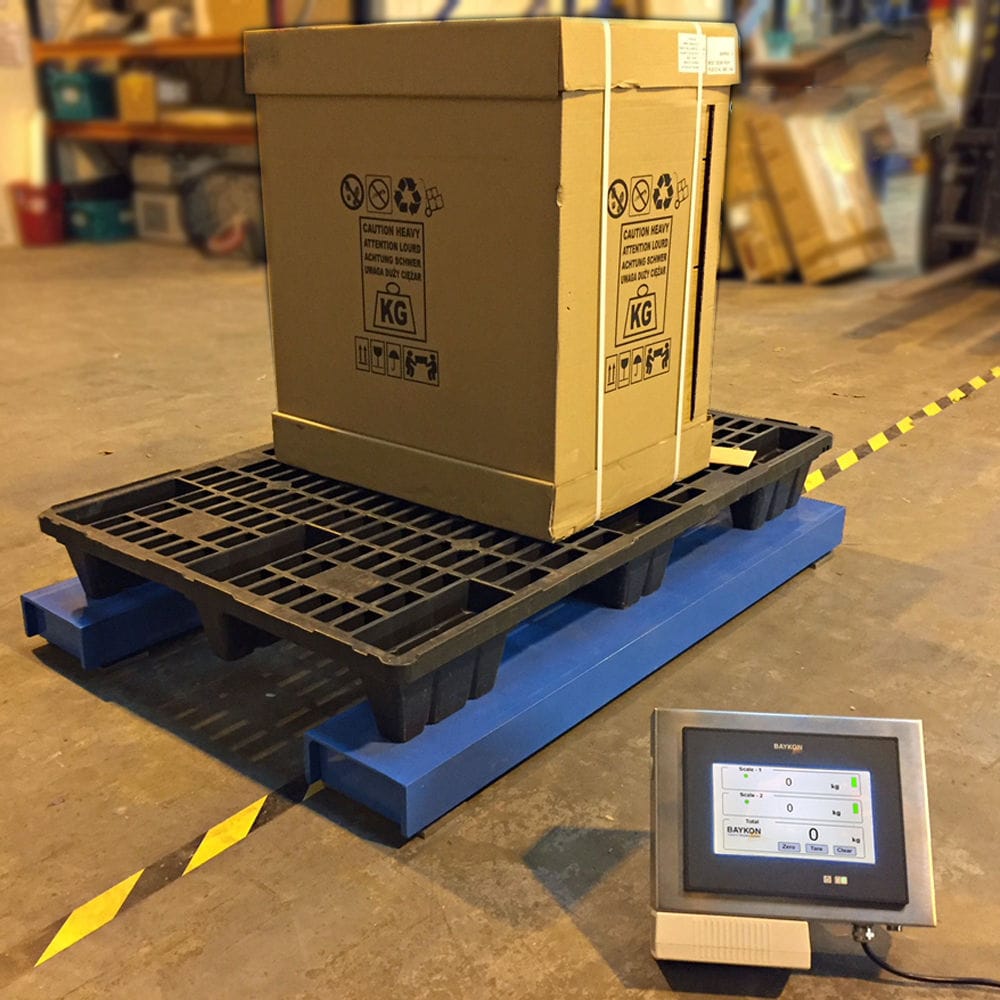


Weighing liquid filling machine through the RS-422/485 interface can be fast communication and setup, hardware configuration and external wiring part of the expansion of analog input and output modules, its programmable controller switching inputs and switching outputs with networking and communication capabilities, you can use the PLC comes with a basic control unit to design its start and stop.

 020-34563445
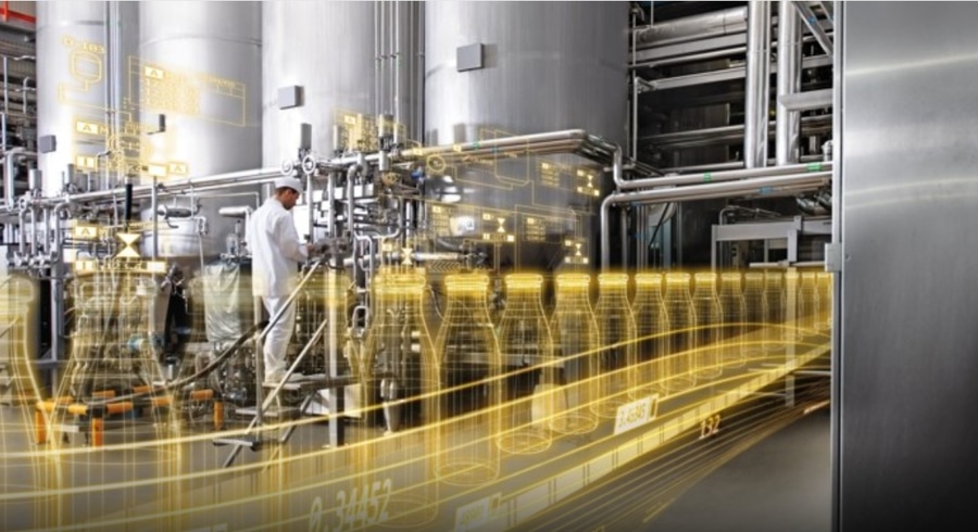
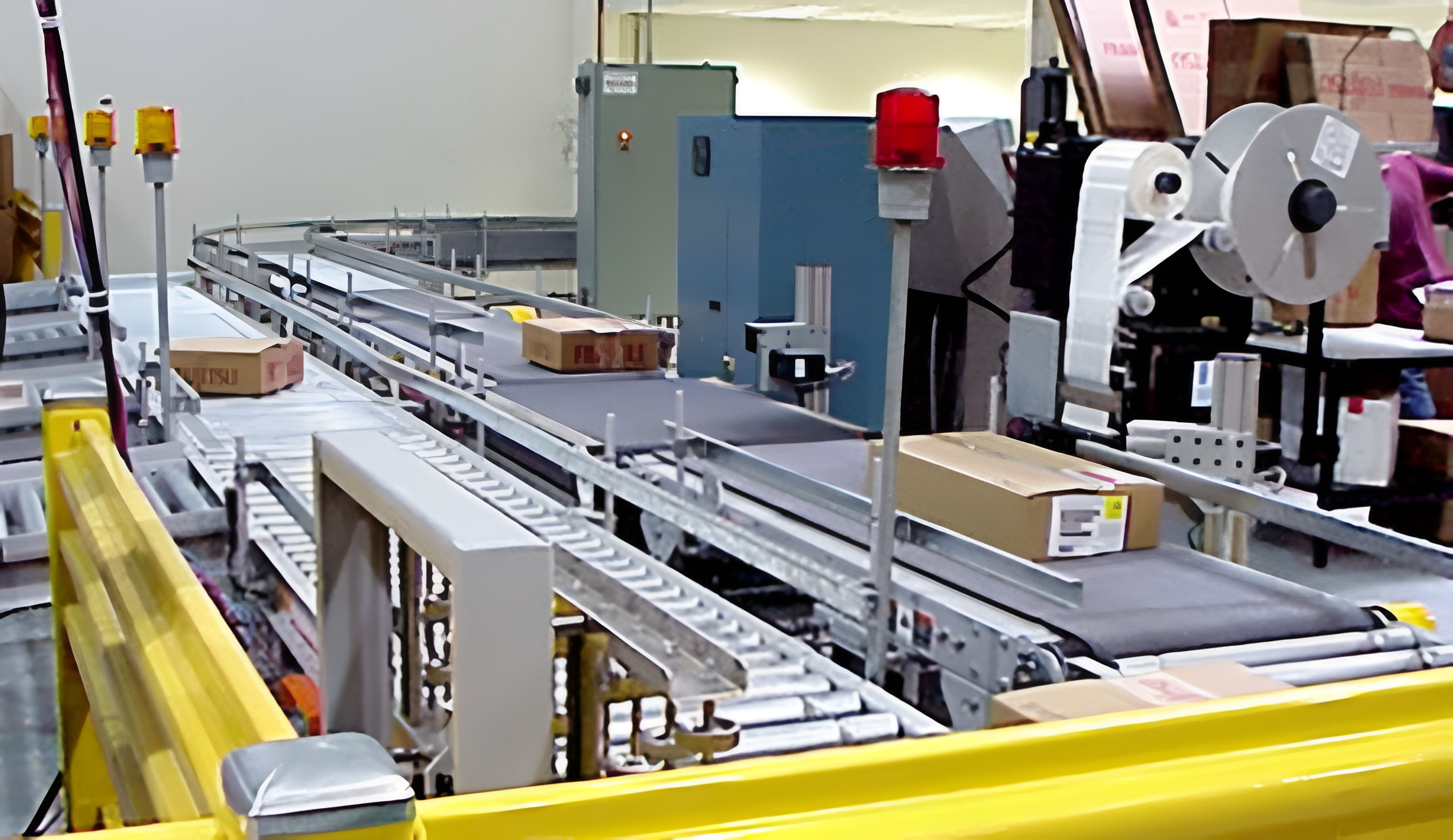
The weighing liquid Filling machine is an automated control system centered around a PLC and a frequency converter, utilizing various sensors and I/O data acquisition cards to perform real-time control and adjustment of the filling actuator. The control objects of the Filling system include the conveyor motors at each production station, protective gas valves, filling valves, lower cap mechanism, and cap pressing mechanism. The collected data includes the levels of storage cylinders and online bottles, protective gas pressure, liquid flow rate during filling, speed of empty/full bottle conveyor belts, and the status of empty and full bottles in place, blockage, lower cap, and opening/closing of the piston valve. The automatic filling machine consists of a conveyor belt and a filling liquid tank, with the conveyor belt driven by a motor. The motor can rotate in both forward and reverse directions. When the motor rotates in the forward direction, the cans are conveyed through four stations in sequence: empty can position, filling position, full can position, and terminal position. The control panel of the weighing filling machine includes both a common lower-level control panel equipped on the filling control console and an upper-level HMI (Human-Machine Interface) device, both of which can control the automatic filling machine. The lower-level control panel uses a common control panel, which requires the design of start and stop buttons, emergency stop buttons, lower-level (PLC)/upper-level (HMI) selection switches, manual/automatic selection switches, forward/reverse jog switches, fault reset buttons, counters, count reset buttons, and various indicator lights. The upper-level HMI device requires the use of a TP177BcolorPN/DP touch screen as the control device. The entire system requires the lower-level control to be managed by a Siemens programmable controller S7-300, and the upper-level computer requires the use of configuration software WinccFlexible to dynamically reproduce the on-site status in graphics, tables, curves, etc. on the TP177BcolorPN/DP touch screen for on-site monitoring. The Siemens MM440 series frequency converter is used to drive the conveyor belt motor, and it is required that the programmable controller S7-300 can communicate and control the frequency converter through a Profibus-DP network, with the frequency converter driving the motor. The weighing filling machine needs to be designed with both manual and automatic working modes. The manual mode is used for equipment debugging and resetting of the full can count value. The automatic mode allows the weighing filling machine to be started and operated. The control system should have emergency handling capabilities as well as fault diagnosis and display alert functions. When equipment malfunctions, the control system can respond immediately by flashing the corresponding indicator light on the control panel or HMI. After the fault is resolved, the filling machine can only operate automatically after pressing the fault reset button.
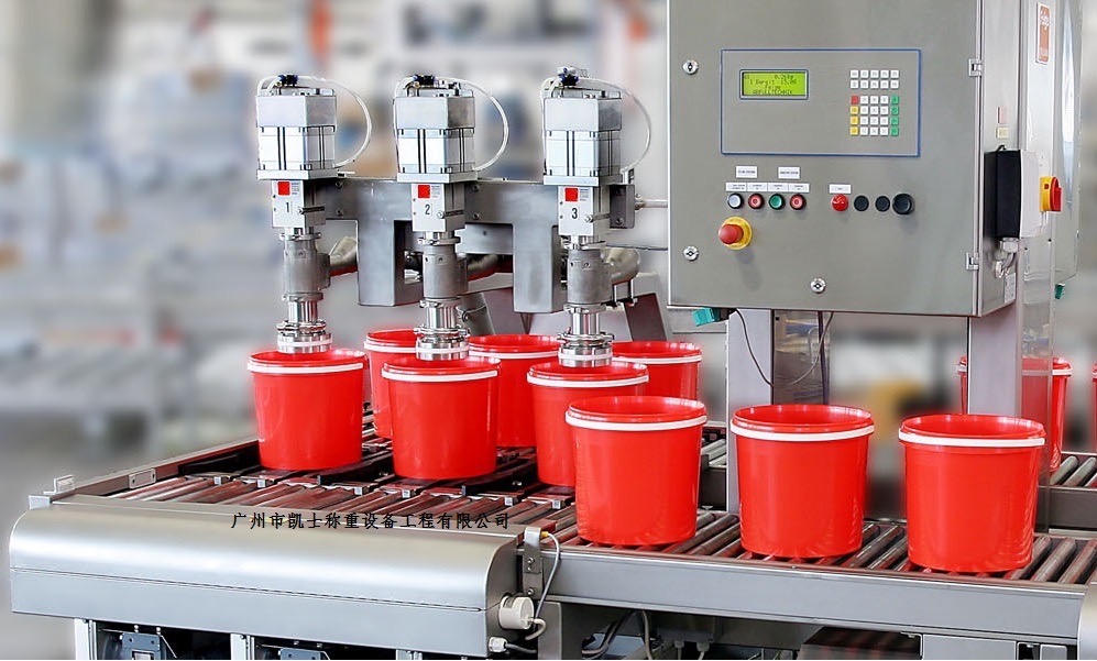
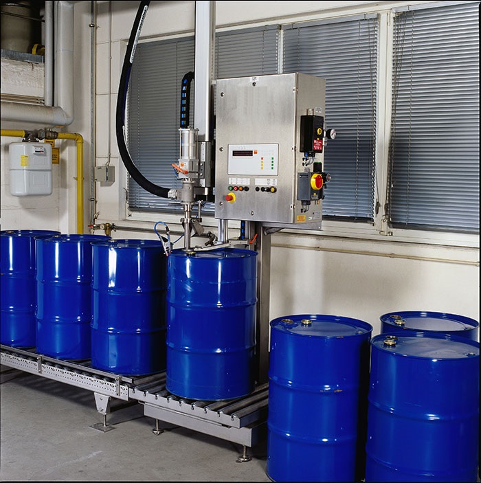
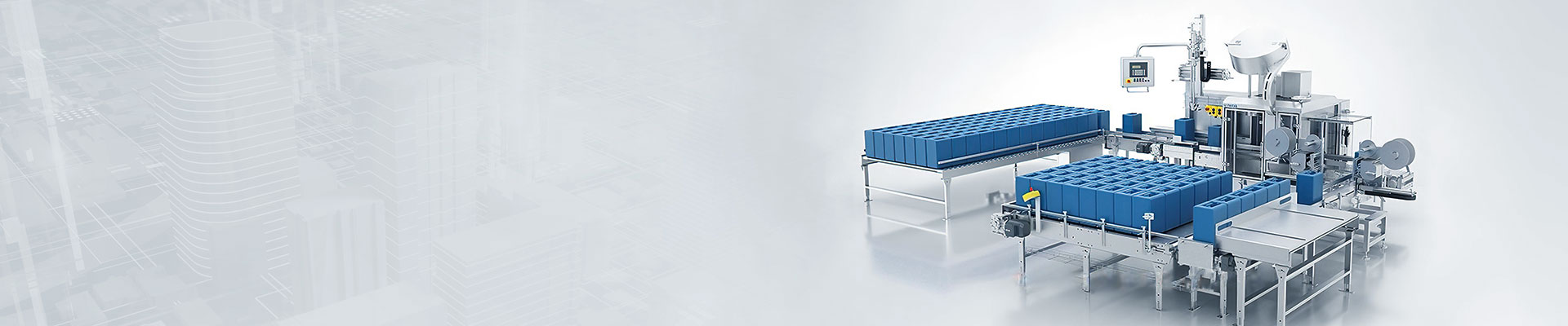
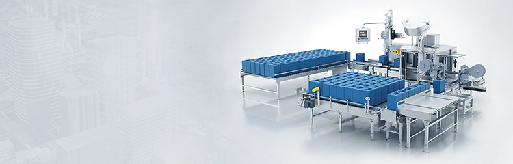
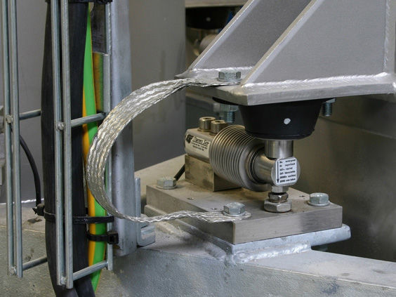
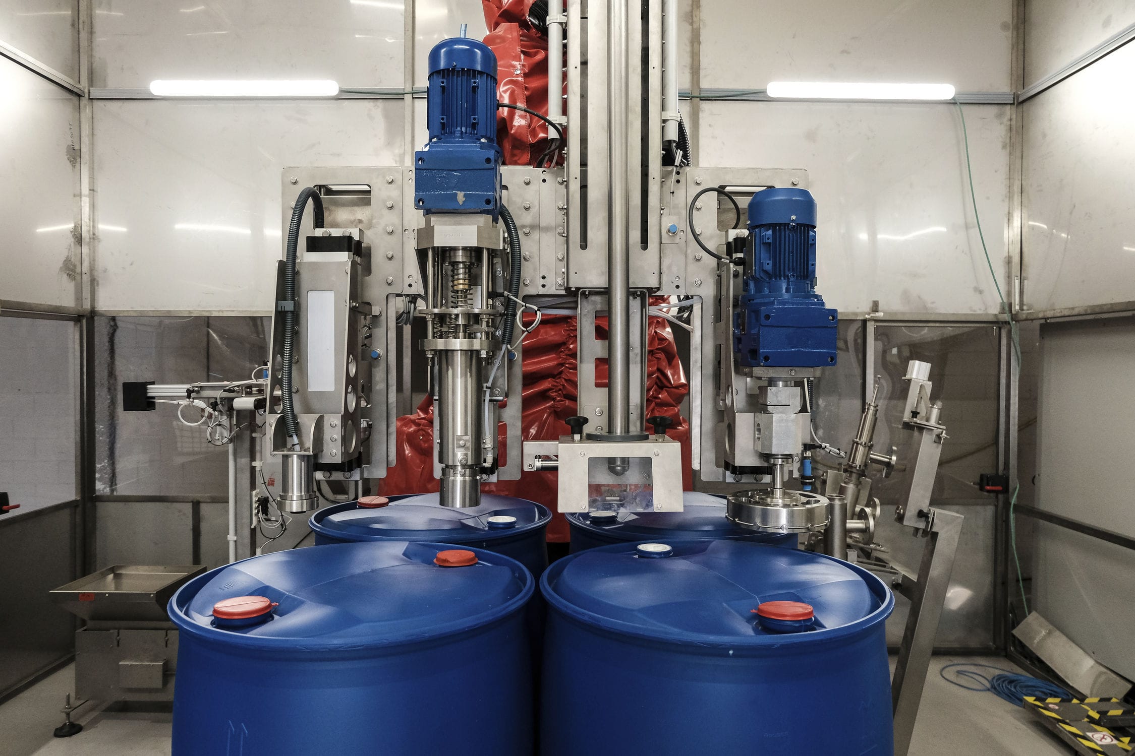
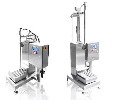
The automatic filling machine, controlled by a PLC, primarily consists of a hopper, a filling piston valve, a barrel-pushing mechanism, an inlet roller conveyor, a weighing mechanism, an outlet roller conveyor, and a control box. The PLC controls the feeding of empty barrels, the filling through the filling valve, the weighing by an electronic weighbridge, and the output of finished products, completing one filling process. The hopper is designed with a feeding mechanism, and the position of the float ball inside the hopper is set with two values: a minimum and a maximum. When the float ball is at the minimum value, feeding commences; when it rises to the maximum value, feeding ceases. The Liquid filling machine utilizes a filling valve seat body and a valve core with a valve core rod. The valve seat body is equipped with a valve core hole, and the bottom of the valve core is fitted with a conical surface. A through hole runs vertically from the middle of the valve core rod to the valve core. The valve core hole consists of an upper cylindrical hole and a lower conical hole. The conical surface at the bottom of the valve core and the conical hole within the valve core hole form the liquid outlet. A corresponding valve seat sleeve is positioned within the upper cylindrical hole of the valve core hole, and the valve core is housed within the sleeve of the valve seat sleeve. The through hole at the lower end of the valve core is connected to an exhaust rod, and an air outlet hole is cut on the side of the valve core, communicating with the through hole in its middle. A connecting hole is cut below the wall of the valve seat sleeve opposite the air outlet hole, and an exhaust hole is cut within the valve seat body corresponding to the connecting hole. The exhaust hole is equipped with a control valve at its outlet. Additionally, an air inlet hole, communicating with the conical hole, is cut within the valve seat body, and a control valve is also positioned at the other end of the air inlet hole. The filling valve is driven by a dual-position air cylinder, facilitating two-stage filling. When a barrel is fed onto the inlet roller conveyor, a photoelectric switch detects its position, prompting the barrel-pushing cylinder to move and push the empty barrel onto a non-powered roller within the weighing mechanism. Once the photoelectric switch detects that the barrel has reached the filling position, the filling valve fully opens to commence filling. When the filling weight reaches the set initial weight, the filling valve partially opens for filling; when the filling weight reaches the set weight, that is, the required filling weight, the filling valve fully closes. The barrel-pushing cylinder moves to position the next empty barrel, which then pushes the filled barrel from the weighbridge position to the conveying position, that is, onto the conveyor for further transportation.
Basic Parameters:
Maximum weighing capacity: 30kg
Minimum sensing capacity: 10g
Filling error: ±10-20g (depending on filling speed)
Filling speed: 100-150 barrels/hour (depending on the feed flow rate)
Applicable containers: small-mouth barrels and open-top barrels with a diameter of ≤Ф350mm and a height of ≤500mm
Explosion-proof grade: EXdiaIIBT4
Power supply: AC220/50Hz
Air source used: 0.4-0.8Mpa
Operating temperature: -10℃-40℃
Control mode: 2-position pneumatic control
Filling method: insertion type, above the liquid level
Scale platform size: 400×400mm
Temporary storage table: 400×1000mm
Material of construction: SUS304 stainless steel.
Gun head pipeline: SUS304 stainless steel and PTFE (optional 316L)
Material interface: DN40 quick-release pagoda connector, with flange connector as an option.
Air source interface: 8mm air tube connection