


The signals measured by the variable-frequency tension weighing module are processed by their own processor through filtering, amplification, and conversion, and then transmitted to the analog input port of the PLC, which is shown in the figure as the tension feedback value. After the tension feedback value is calculated with the tension set value input from the touch screen, a tension deviation value is obtained. This tension deviation value is processed by the PID controller to obtain a control quantity. The program converts this control quantity into the control word for the frequency converter and transmits it to the traction frequency converter through the PLC. The traction frequency converter then adjusts the speed of the traction motor, thereby achieving the constant tension control of the sheet material. In the program, it is possible to set that the PID controller is used when the tension feedback value approaches 90% of the tension set value. This can increase the response speed of the system.

 020-34563445
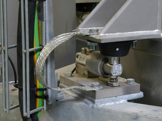
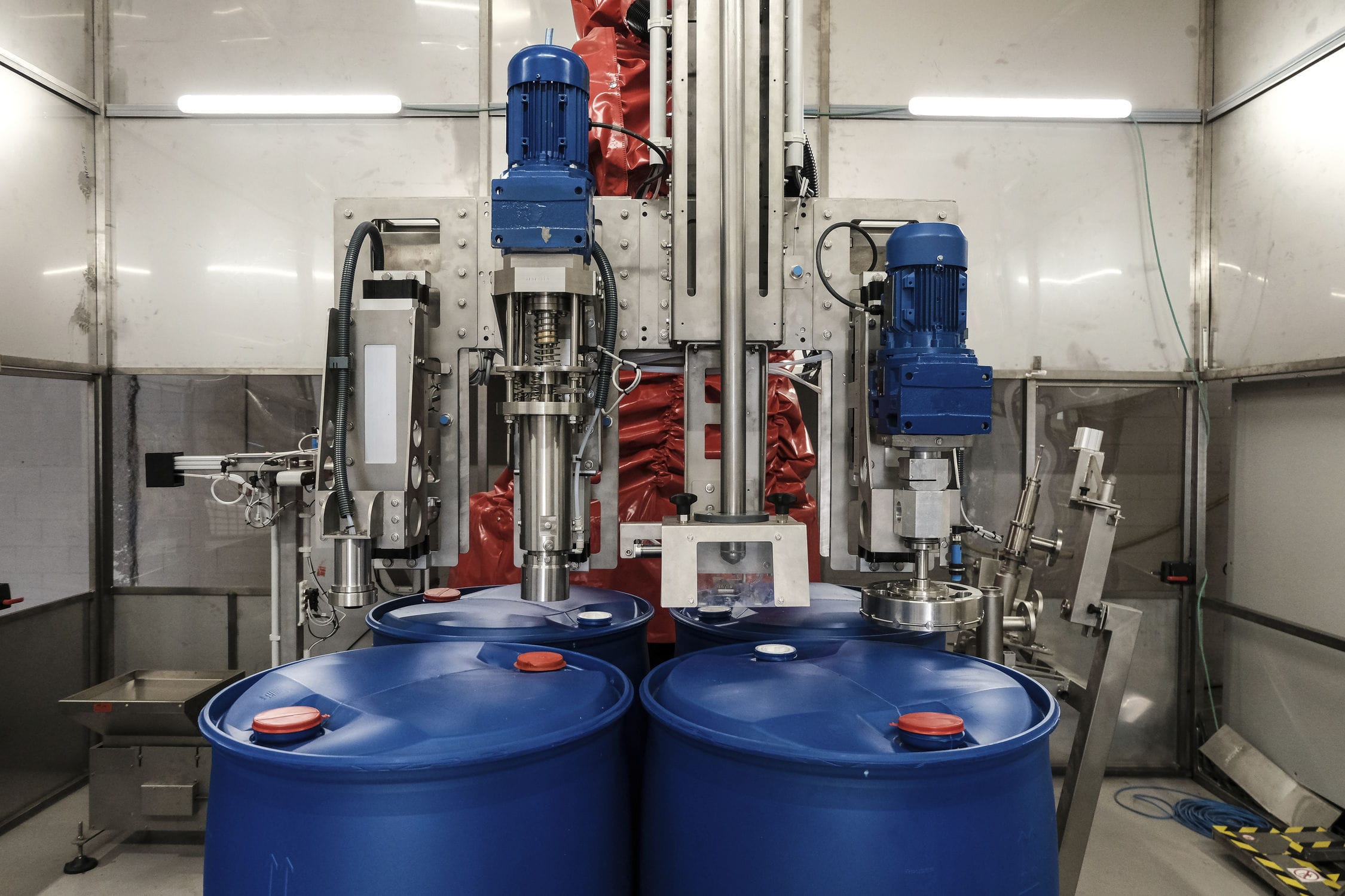
The variable frequency tension weighing module controls the constant tension and constant speed winding control with PLC as the control core, and AC synchronous servo motor as the actuator. The tension and line speed feedback values are obtained through the weighing module and incremental encoder. After being processed by PLC, the rotational speeds of the winding roller and unwinding drum motors are controlled respectively to achieve the control of constant tension and constant speed. The automatic winding and unwinding system mainly consists of winding roller, unwinding roller, tensioning roller, weighing module drive system and synchronous servo motor. The measuring and weighing module for the winding line speed of the material rolls is controlled to rotate the unwinding drum motor by the incremental encoder and PLC; the tension signal feedback is selected as the cantilever weighing module, which converts and outputs a standard +10V voltage signal through the weighing transmitter, and then the feedback tension is collected by the analog input module of PLC. All the functional operations, parameter settings and monitoring screens of the control system are realized on the touch screen; at the same time, the system also includes safety light curtains, emergency stop buttons, stop when the roll diameter is too small, and stop when the tension is too high, etc. as protection functions.
The purpose of micro-tension control is to allow the rolled pieces between the upper and middle sections of the coarse and medium motor groups to be rolled under a very small tension. In the production of winding and unwinding drums, the "current-speed" indirect micro-tension control method is generally adopted. The change in tension is caused by the difference in the second flow rate of the wire, and adjusting the speed of the motor can change the second flow rate, thereby achieving the purpose of controlling the tension. By detecting the torque of the upper motors of the adjacent two working sections and storing it for memory, the actual value representing the internal tension of the winding is formed. It is compared with the set tension setpoint to determine the deviation, and the speed of the upstream section is corrected through proportional and integral control to coordinate the relationship between the two sections and achieve micro-tension control. The key to the control is to accurately measure the rolling current (i.e., torque) of each motor. The Weighing system indirectly obtains this value by detecting the armature torque of the corresponding section. When the rolled piece of this section is wound and has not yet entered the motor of the lower section, the calculated torque value by the system is the rolling torque value of this motor. When the motor of the lower section also starts winding, a new torque is calculated, and the difference between the two torques is the tension torque on the rolled piece. The system uses the positive or negative sign and magnitude of the deviation value to give the corresponding speed correction to balance the speed of the motors and ensure that the tension between the sections is limited within a certain range, achieving micro-tension control.
The signals measured by the tension measurement module are processed by their own processor through filtering, amplification, and conversion, and then transmitted to the analog input port of the PLC, which is shown in the figure as the tension feedback value. After the tension feedback value is calculated with the tension set value input from the touch screen, a tension deviation value is obtained. This tension deviation value is processed by the PID controller to obtain a control quantity. The program converts this control quantity into the control word for the frequency converter and transmits it to the traction inverter through the PLC. The traction inverter then adjusts the speed of the traction motor, thereby achieving the constant tension control of the sheet material. In the program, it is possible to set that the PID controller is used when the tension feedback value approaches 90% of the tension set value. This can increase the response speed of the system.


